Cycloid type reducer

A reducer and cycloid technology, applied in mechanical equipment, elastic couplings, transmission parts, etc., can solve the problems of idling phenomenon, reduced assembly efficiency, prolonged assembly time, etc., to increase rigidity and positioning accuracy, The effect of avoiding empty travel and reducing assembly time

Active Publication Date: 2019-03-26
HIWIN TECH
View PDF8 Cites 2 Cited by
  • Summary
  • Abstract
  • Description
  • Claims
  • Application Information

AI Technical Summary

Problems solved by technology

However, since the side walls of the groove of the cycloid wheel, the side wall of the output element groove and the side wall of the cross Odan are all parallel to the axial direction, the rolling elements are first placed on the groove side of the cycloid wheel during assembly. Put the cross-oldan on the wall, or put the rolling element on the side wall of the cross-oldan first and then put the output element. Both methods are very easy to collide with the rolling element during assembly, which will not only cause the rolling element It must be reassembled due to overturning, resulting in reduced assembly efficiency and prolonged assembly time, and may cause damage to rolling elements, cycloidal wheels, cross Odan and output elements
[0004] Therefore, the current solution is to increase the width of the groove between the cycloidal wheel and the output element to facilitate the placement and assembly of the rolling elements, but in this way, not only will the gap between the elements be too large, but the transmission As the backlash increases, there will be problems such as lost motion during forward and reverse rotation, poor positioning accuracy, and increased collision noise.

Method used


Image

  • Cycloid type reducer
  • Cycloid type reducer
  • Cycloid type reducer

Examples


Embodiment Construction

[0032] In order to achieve the above-mentioned purpose and effect, the technical means and structure adopted by the present invention are described in detail below in conjunction with the accompanying drawings:

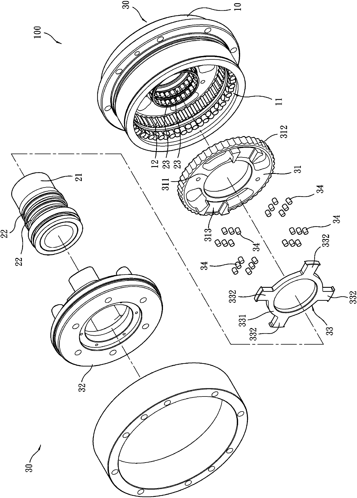
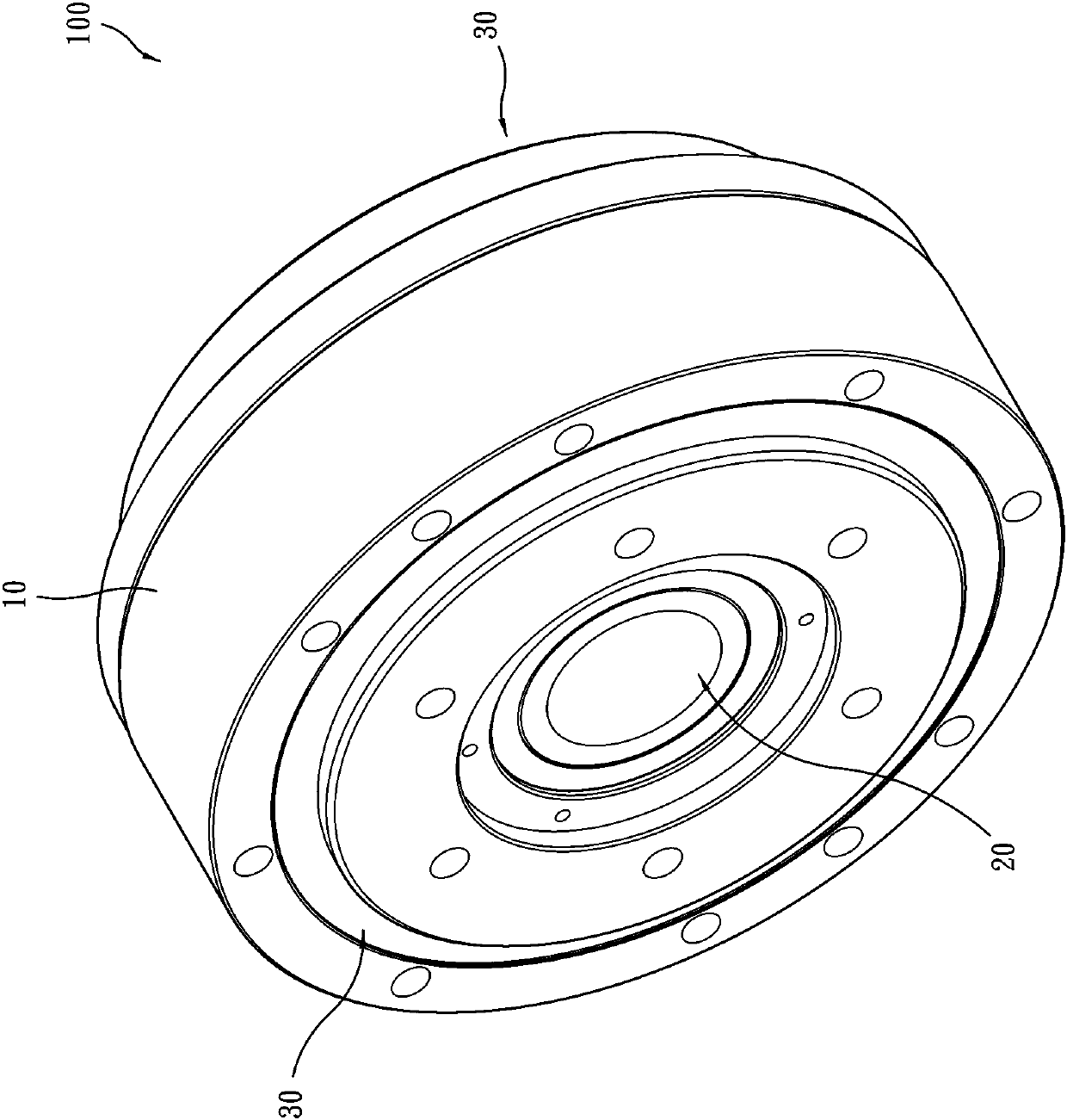
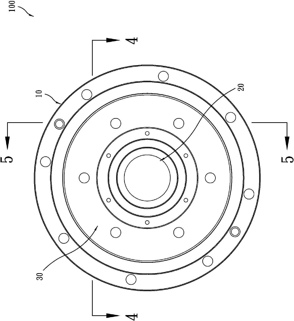
[0033] Such as Figure 1 to Figure 5 As shown, a cycloidal reducer 100 provided by a preferred embodiment of the present invention mainly includes a main body 10, an input shaft sleeve 20 and two deceleration output units 30, wherein:

[0034] The main body 10 has an axial assembly hole 11 and an annular inner tooth 12 formed on the inner peripheral surface of the axial assembly hole 11 .

[0035] The input shaft sleeve 20 has a shaft sleeve 21 , two eccentric sleeves 22 mounted on the shaft sleeve 21 and two bearings 23 respectively mounted on the eccentric sleeves 22 . The input sleeve 20 is placed in the axial assembly hole 11 of the main body 10 for inputting a deflection force.

[0036] The two deceleration output units 30 are arranged in the axial assembly hol...


PUM


Abstract

The invention relates to a cycloid type reducer. The cycloid type reducer comprises a main body, an input shaft sleeve and two deceleration output units. Each deceleration output unit is separately provided with a cycloid wheel, an output element, a cross oldham and a plurality of rolling elements, and the cycloid wheels sleeve the input shaft sleeve. The cycloid wheels are provided with a plurality of cycloid wheel grooves, and a side groove wall of each the cycloid wheel groove is an oblique surface. A plurality of output element grooves are formed in one end surface of the output elements,the cross oldhams are provided with central ring parts and four binding parts bulging in a cross shape, and one side wall of each output element is an oblique surface. The two binding parts of the cross oldhams are placed in the cycloid wheel grooves of the cycloid wheels, the other two binding parts are placed in the output element grooves of the output elements, the rolling elements are separately placed between the oblique surfaces of the cycloid wheels and the oblique surfaces of the cross oldhams, and between the groove walls of the output element grooves and the side walls of the bindingparts of the cross oldhams. The effects that the assembly efficiency is good, transmission back gaps are reduced, an idle running phenomenon is avoided, the positioning accuracy is good, and collision noise is reduced are realized.

Description

technical field [0001] The invention relates to a cycloid reducer, in particular to a cycloid reducer capable of improving assembly efficiency and reducing assembly cost. Background technique [0002] Cycloidal reducer is a common reduction mechanism. Its principle is to achieve deceleration output through eccentric input and gear difference transmission. [0003] However, the structure of the general cycloidal reducer is to use the cross Odan for non-coaxial connection transmission between the cycloid wheel and the output element (flange), so it must be connected between the cycloid wheel and the cross Odan and between the cross Odan Rolling elements (such as rollers) are set between the Dan and the output element to reduce power loss, that is, both the cycloidal wheel and the output element are provided with grooves for the cross Oudan to be set in, and the rolling element is positioned on the cross Oudan. Between the side wall of the cycloid wheel and the groove side wal...

Claims


Application Information

Patent Timeline
Patent Type & Authority Applications(China)
IPC IPC(8): F16H1/32F16H57/08
CPCF16H1/32F16H57/08F16D3/04F16H2001/326
Inventor 王政隆郑旭珉
Owner HIWIN TECH
Why Eureka
Try Eureka