Automobile fuse box assembly detection system, image recognition method and screw hole positioning method

A technology for fuse box and assembly testing, which is used in measuring devices, optical instrument testing, machine/structural component testing, etc. It can solve problems such as reducing testing efficiency, difficult informatization system integration, and inability to realize interconnection of production lines.

Active Publication Date: 2019-03-26
YUNNAN NORMAL UNIV
View PDF7 Cites 10 Cited by
  • Summary
  • Abstract
  • Description
  • Claims
  • Application Information

AI Technical Summary

Problems solved by technology

The internal structure of the existing automotive fuse box inspection system and assembly system is relatively complicated, making them two independent systems, resulting in a low degree of cooperation between the existing systems, separation of inspection and assembly processes, and taking up valuable resources. Production space also increases the factory's investment in equipment
Moreover, the detection systems currently used in the market have high requirements on the environment due to technical limitations, and need to provide an additional inspection environment without external light interference, which reduces the detection efficiency.
On the other hand, although the current foreign high-end fuse box automatic production system has gradually provided the function of uploading

Method used

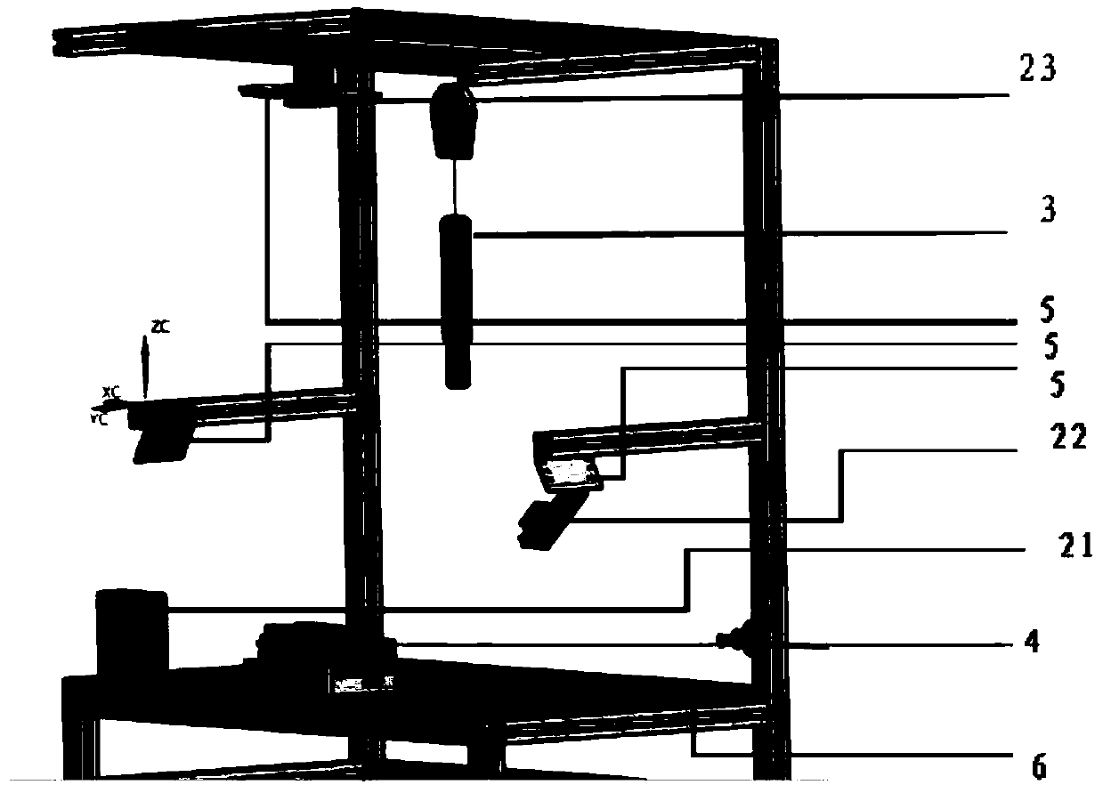
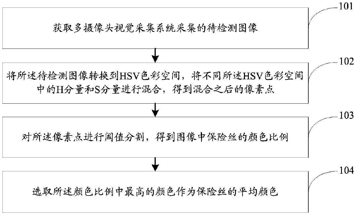
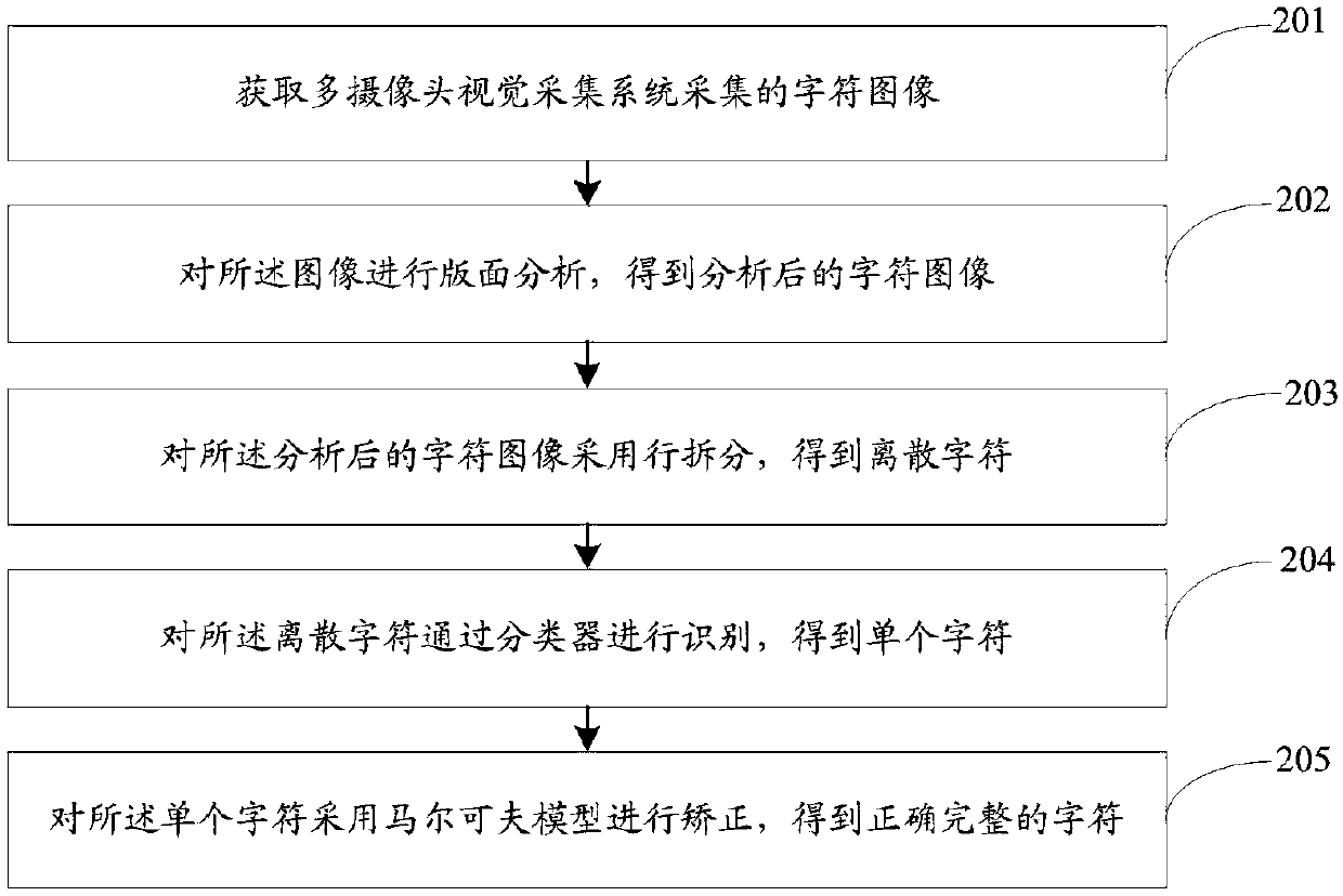

Image

  • Automobile fuse box assembly detection system, image recognition method and screw hole positioning method
  • Automobile fuse box assembly detection system, image recognition method and screw hole positioning method
  • Automobile fuse box assembly detection system, image recognition method and screw hole positioning method

Examples


Embodiment Construction

[0045] The following will clearly and completely describe the technical solutions in the embodiments of the present invention with reference to the accompanying drawings in the embodiments of the present invention. Obviously, the described embodiments are only some, not all, embodiments of the present invention. Based on the embodiments of the present invention, all other embodiments obtained by persons of ordinary skill in the art without making creative efforts belong to the protection scope of the present invention.

[0046] The purpose of the present invention is to provide an automobile fuse box assembly detection system, an image recognition method and a screw hole positioning method, which can improve the detection accuracy and detection efficiency of the automobile fuse box.

[0047] In order to make the above objects, features and advantages of the present invention more comprehensible, the present invention will be further described in detail below in conjunction with...


PUM


Abstract

The invention discloses an automobile fuse box assembly detection system, an image recognition method and a screw hole positioning method. The system comprises a detection platform, a multi-camera visual acquisition system, a program-controlled moment torque wrench and a computer; a fuse box to be detected is located on the detection platform, and the multi-camera visual acquisition system is usedfor obtaining images of the fuse box to be detected from three angles; the program-controlled moment torque wrench is positioned above the fuse box to be detected; the program-controlled moment torque wrench is used for selecting proper force by judging the type of the nut so as to tighten the screw on the fuse box to be detected; and the computer is connected with the multi-camera visual acquisition system and the program-controlled moment torque wrench and is used for receiving the image information acquired by the multi-camera visual acquisition system, identifying whether the fuse is correctly assembled according to the image information, and adjusting the program-controlled moment torque wrench to tighten the nut of the fuse box to be detected. The detection precision and the detection efficiency of an automobile fuse box can be improved.

Description

technical field [0001] The invention relates to the field of automobile fuse box detection, in particular to an automobile fuse box assembly detection system, an image recognition method and a screw hole positioning method. Background technique [0002] Automobile fuse boxes have very strict requirements for inspection and assembly, and there are many types of inspections required for this type of product, and the assembly process is complicated, so that under the current production process, a large number of workers need to be invested in product quality inspection. At the same time, there are connecting parts such as screws and nuts in this type of product, and the coupling degree (that is, the torque of the screw) required by different connecting parts in different positions is not the same, resulting in high labor intensity, high cost and high cost during the assembly process. High reliability cannot be guaranteed. On the other hand, excessive reliance on human labor in...

Claims


Application Information

Patent Timeline
IPC IPC(8): G01M11/00B23P19/06B23P19/10
CPCB23P19/06B23P19/105G01M11/00
Inventor 罗毅杨昆商春雪王伟强邢林
Owner YUNNAN NORMAL UNIV
Why Eureka
Try Eureka