High-current connector

A high-current connector and connector technology, applied in the direction of conductive connection, electrical component connection, connection, etc., can solve the problems of battery electric shock, troublesome installation, large operating space, etc., saving materials and space, easy installation, and volume. small effect

Pending Publication Date: 2019-03-26
YUEQING BADA OPTICAL ELECTRICAL TECH CO LTD +1
View PDF0 Cites 5 Cited by
  • Summary
  • Abstract
  • Description
  • Claims
  • Application Information

AI Technical Summary

Problems solved by technology

[0002] The overall size of the existing new energy vehicle battery pack is limited, and the layout space of the internal module components is small, while the existing high-voltage and high-current connectors are used outside the battery pack, and the installation space and the required operating space are relatively large, which cannot meet the requirements. Battery Pack Internal Requirements
[0003] The battery module module connectors in the existing battery pack are directly connected to the output pole of the module module and the output copper bar through screws, which is troublesome to install and does not have the function of preventing electric shock. There is a risk of electric shock due to the positive output of the module with anti-electric shock function
The high-current connector that meets the function of preventing electric shock has a complex structure and high cost
[0004] The output direction of most existing connections is fixed, and the output direction of the connector cannot be adjusted 360° according to the demand.

Method used


Image

  • High-current connector
  • High-current connector
  • High-current connector

Examples


Embodiment Construction

[0029] The present invention will be described in detail below in conjunction with the embodiments and the accompanying drawings. It should be noted that the described embodiments are only intended to facilitate the understanding of the present invention, rather than limiting it in any way.

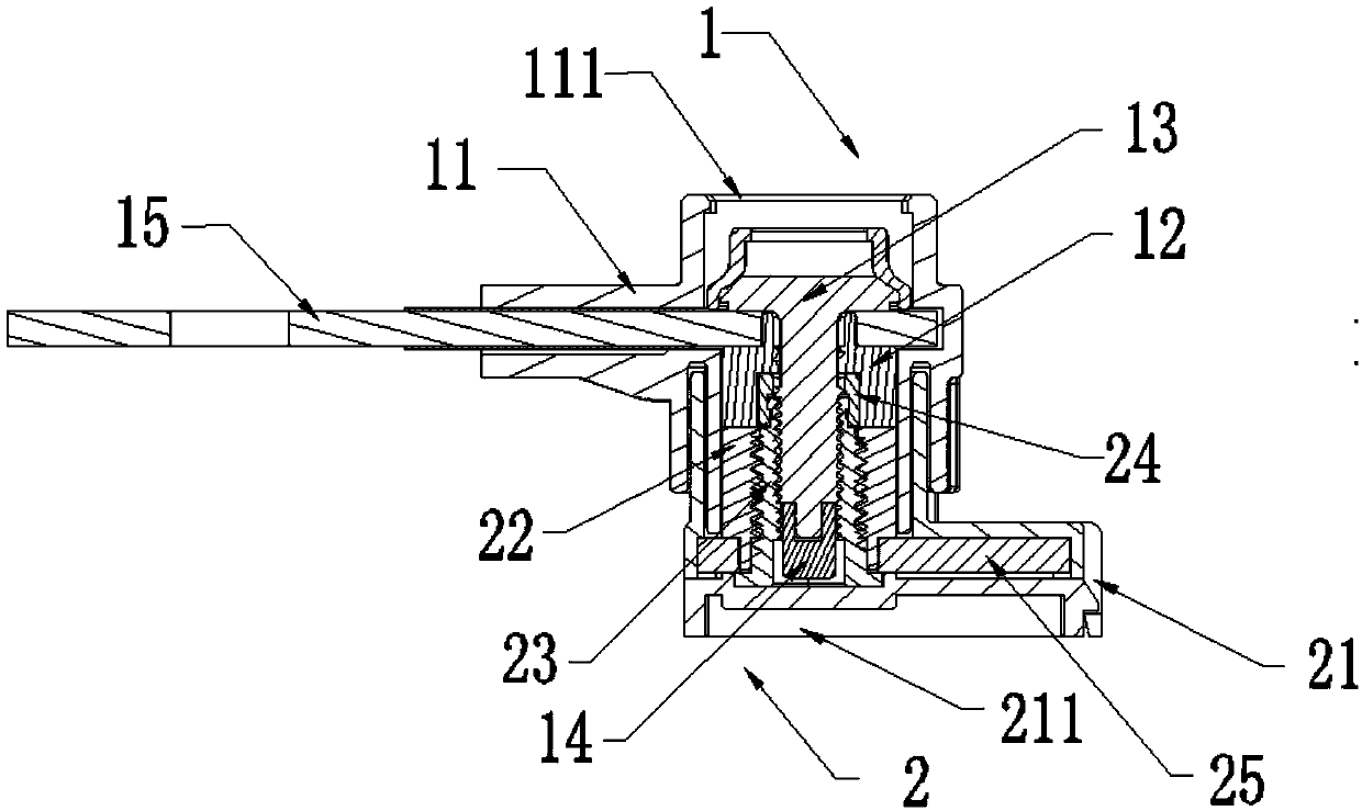
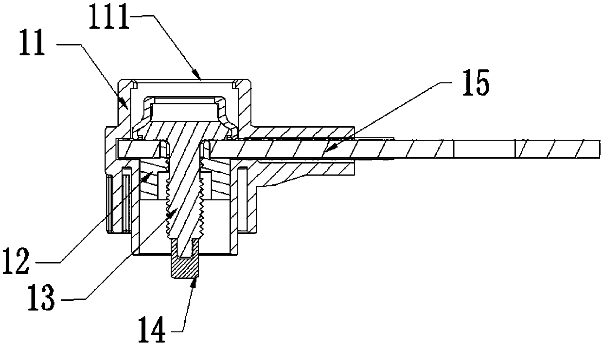
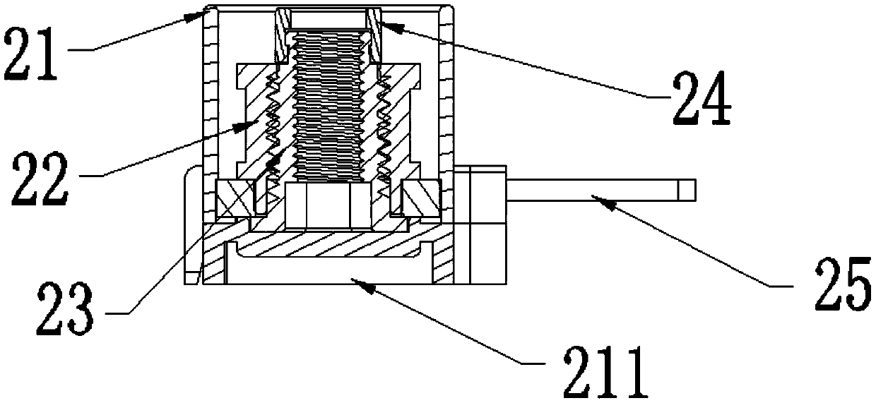
[0030] Such as Figure 1-7 As shown, according to this embodiment, a high-current connector is provided, including an input part 1 and an output part 2. The input part 1 includes a first housing 11, an input contact 12 and a fastener 13, and the input contact 12 is provided with There is a connection hole, the output part 2 includes a second housing 21, an output contact 22 and a connection seat 23, and the output contact 22 is sleeved on the connection seat 23; when the input part and the output part are connected, one end of the fastener 13 passes through The connection hole is fixed on the connection seat 23 , and the other end is limited on the first housing 11 or the input contact 12...


PUM


Abstract

The present invention relates to a high-current connector comprising an input portion and an output portion. The input portion includes a first housing, an input contact and a fastener. The input contact is provided with a connection hole. The output portion includes a second housing, an output contact and a connection seat. The output contact sleeves the connection seat. When the input portion isconnected to the output portion, one end of the fastener passes through the connecting hole to be fixed to the connection seat, the other end of the fastener is restricted to the first housing or theinput contact, and the input contact is in conductive contact with the output contact. The input portion and the output portion are connected by a screw and a nut in an over-locking connection mode.The high-current connector is easy to install, saves material and space, and is not loose in the case of vehicle vibration, has an IPXXB anti-electric shock function under the premise of a small sizeand a large current carrying capacity. The output direction of the connector can be adjusted as required with in 360 degrees.

Description

technical field [0001] The invention relates to a connector, in particular to a high-current connector. Background technique [0002] The overall size of the existing new energy vehicle battery pack is limited, and the layout space of the internal module components is small, while the existing high-voltage and high-current connectors are used outside the battery pack, and the installation space and the required operating space are relatively large, which cannot meet the requirements. Internal requirements of the battery pack. [0003] The battery module module connectors in the existing battery pack are directly connected to the output pole of the module module and the output copper bar through screws, which is troublesome to install and does not have the function of preventing electric shock. The module with anti-shock function outputs positive pole and there is a risk of electric shock. The high-current connector that meets the function of preventing electric shock has a...

Claims


Application Information

Patent Timeline
Patent Type & Authority Applications(China)
IPC IPC(8): H01R13/506H01R13/621H01R35/00H01R13/642
CPCH01R13/506H01R13/6215H01R13/642H01R35/00H01R11/283H01R11/288H01R13/44
Inventor 邬昌荣陈雪黎欢乐
Owner YUEQING BADA OPTICAL ELECTRICAL TECH CO LTD
Why Eureka
Try Eureka