Cervical dilator with unilateral distraction function

A dilator and cervical technology, applied in the field of dilators, can solve the problems of poor dilating effect, high manufacturing cost, and weak structural rigidity, and achieve the effects of simple and practical structure, avoiding cervical damage, and good structural rigidity

Pending Publication Date: 2019-03-29
LISHUI PEOPLES HOSPITAL
View PDF1 Cites 2 Cited by
  • Summary
  • Abstract
  • Description
  • Claims
  • Application Information

AI Technical Summary

Problems solved by technology

[0002] At present, in many uterine operations, the cervix needs to be dilated, and the cervix is ​​often small, and medical instruments cannot be inserted into the cervix.
Existing cervical dilators are various rod-type devices of different thicknesses, which require repeated operations to allow the contractile cervix to expand naturally under external pressure, which is very inconvenient; another rod-type dilator contacts and rubs against the inner wall of the cervix many times. , it is easy to cause cervical damage, and the expansion effect is very poor
A cervical dilator is disclosed in the patent No. CN201410533294.4, which includes an expansion head,

Method used


Image

  • Cervical dilator with unilateral distraction function
  • Cervical dilator with unilateral distraction function
  • Cervical dilator with unilateral distraction function

Examples


Embodiment 1

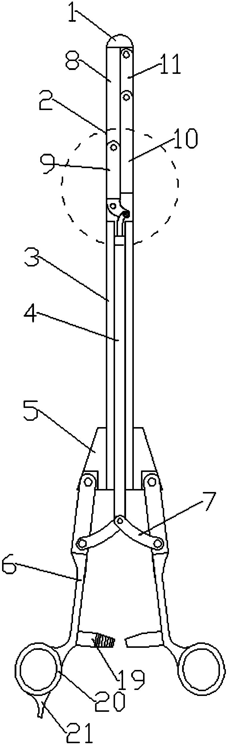
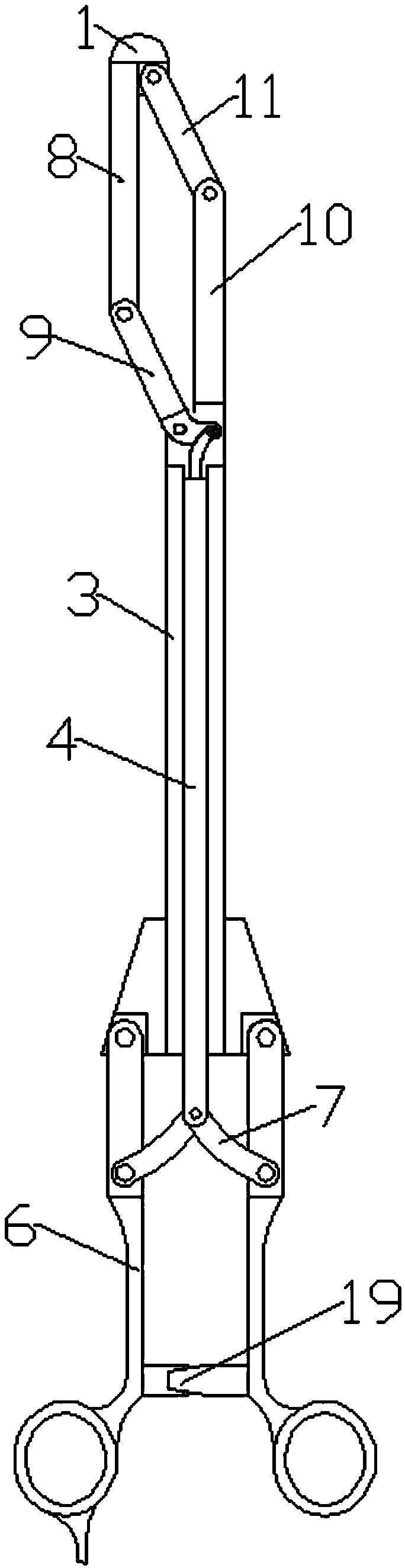
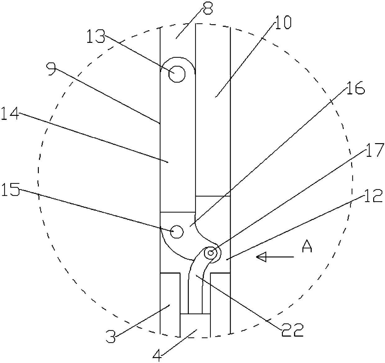
[0024] Embodiment 1: An elastic rod 22 is fixed on the upper end of the inner core 4 , and the top of the elastic rod 22 is hinged to the force application point 17 of the active rocker 9 . When in use, first the handle 6 is in a separated state, and the expansion frame 2 is in a closed state. When the dilator is inserted into the cervix, since the expansion head 1 is provided at the front end of the expansion frame 2, the cervix will not be damaged, and the cervix will not be damaged. an expansion. When the expansion frame 2 is outside the inner wall of the cervix, the hand presses the handle 6, the handle 6 is closed, the bead 7 is tightened, the inner core 4 is pushed forward, and when the inner core 4 is pushed forward, the elastic rod 22 bends and pushes the force Transferred to the force point 17 of the power arm 16, the active rocker 9 rotates around the fulcrum 15, and the resistance arm 14 is opened. Since the expansion frame 2 is a parallel double rocker mechanism, t...

Embodiment 2

[0025] Embodiment 2: A connecting rod 18 is provided between the force application point 17 and the upper end of the inner core 4, and the upper and lower ends of the connecting rod 18 are respectively hinged to the force application point 17 and the upper end of the inner core 4. When in use, first the handle 6 is in a separated state, and the expansion frame 2 is in a closed state. When the dilator is inserted into the cervix, since the expansion head 1 is provided at the front end of the expansion frame 2, the cervix will not be damaged, and the cervix will not be damaged. an expansion. When the expansion frame 2 is outside the inner wall of the cervix, the hand presses the handle 6, the handle 6 is closed, the bead 7 is tightened, the inner core 4 is pushed forward, and when the inner core 4 is pushed forward, the connecting rod 18 deflects and moves to the right And the force is transmitted to the force point 17 of the power arm 16, the active rocker 9 rotates around the ...

Embodiment 3

[0026] Embodiment 3: The force application point 17 is a structure of an inclined chute 23 , and a first rotating shaft 24 is arranged inside the inclined chute 23 , and the first rotating shaft 24 is fixed on the upper end of the inner core 4 . When in use, first the handle 6 is in a separated state, and the expansion frame 2 is in a closed state. When the dilator is inserted into the cervix, since the expansion head 1 is provided at the front end of the expansion frame 2, the cervix will not be damaged, and the cervix will not be damaged. an expansion. When the expansion frame 2 is outside the inner wall of the cervix, the hand presses the handle 6, the handle 6 is closed, the bead 7 is tightened, the inner core 4 is pushed forward, and when the inner core 4 is pushed forward, the first rotating shaft 24 advances and Sliding in the inclined chute 23, the force is transmitted to the power arm 16, the active rocker 9 rotates around the fulcrum 15, and the resistance arm 14 is ...


PUM


Abstract

The invention discloses a cervical dilator with a unilateral distraction function. The cervical dilator comprises a tube body, wherein an inner core is arranged in the tube body; a dilating rack is arranged at the top of the tube body; a dilating head is arranged at the top of the dilating rack; the bottom end of the tube body is mounted on a support; a handle is hinged to each of two sides of thebottom of the support; a press bar is arranged on each handle, the press bars located on the two sides are symmetrically inclined and hinged to the lower end of the inner core together; the upper endof the inner core is connected with the dilating rack; the dilating rack is a parallel double-rocker mechanism and comprises a driving rocker, a rack rod, a driven rocker and a side stay connecting rod, the driving rocker is of a lever structure, a power arm is a side hook structure formed by the bottom end, bulging to the lower right, of a resisting arm, a force bearing point, a fulcrum and a force application point are not located in the same straight line, and the force application point and the upper end of the inner core are connected through a live hinge. The cervical dilator is good indilating effect, outward unilateral distraction of the cervix uteri is realized by the side stay connecting rod, and cervix uteri injury caused by common dilating is avoided.

Description

technical field [0001] The invention relates to a dilator, in particular to a single sided cervical dilator. Background technique [0002] At present, in many uterine operations, the cervix needs to be dilated, and the cervix is ​​often small, and medical instruments cannot be inserted into the cervix. Existing cervical dilators are various rod-type devices of different thicknesses, which require repeated operations to allow the contractile cervix to expand naturally under external pressure, which is very inconvenient; another rod-type dilator contacts and rubs against the inner wall of the cervix many times. , It is easy to cause cervical damage, and the expansion effect is very poor. A cervical dilator is disclosed in the patent No. CN201410533294.4, which includes an expansion head, an expansion frame, an inner core, a connecting rod and handles on both sides connected to each other in sequence, and the rear end of the expansion head is connected with the The expansion ...

Claims


Application Information

Patent Timeline
IPC IPC(8): A61B17/42A61M29/00
CPCA61B17/42A61B2017/4225A61M29/00A61M2210/1433A61M2210/005
Inventor 赖晓珺杨金良
Owner LISHUI PEOPLES HOSPITAL
Why Eureka
Try Eureka