
Hanging system of rail car

A rail vehicle and suspension technology, which is applied in the field of rail vehicle suspension systems, can solve the problems of equipment falling off, corrosion, and low stability, and achieve the effects of convenient installation and operation, simple overall structure, and good stability

Inactive Publication Date: 2019-03-29
CRRC QINGDAO SIFANG CO LTD
View PDF4 Cites 0 Cited by
  • Summary
  • Abstract
  • Description
  • Claims
  • Application Information

AI Technical Summary

Problems solved by technology

[0002] At present, the urban rail suspension device mainly adopts the following methods: using anti-off board, steel wire rope, chain, bolt assembly and other structures. Among them, the anti-off board needs to occupy a large installation space and has high requirements for the installation position, so it is not suitable for application in On rail vehicles, when steel wire ropes or chains are used, due to the relative movement between the car body and the horizontal beam, it is necessary for the steel wire ropes or chains to have a considerable margin. At this time, under certain conditions, they will sag and touch The horizontal beam will cause the horizontal beam to be worn and corroded, and even cause a fracture accident. The chassis equipment is directly hung on the lower surface of the chassis beam through bolts and bolt assemblies. When the bolt breaks, because the equipment has no anti-off protection , will cause the equipment to fall off. This kind of hanging method has certain safety hazards and is easy to cause safety accidents. Only the method of hanging above is used to support the car body, and the stability is low.

Method used


Image

  • Hanging system of rail car
  • Hanging system of rail car

Examples


Embodiment Construction

[0022] In order to make the purpose, technical solutions and advantages of the embodiments of the present invention more clear, the technical solutions in the embodiments will be clearly and completely described below in conjunction with the accompanying drawings in the embodiments of the present invention. The following embodiments are used to illustrate the present invention , but not to limit the scope of the present invention.

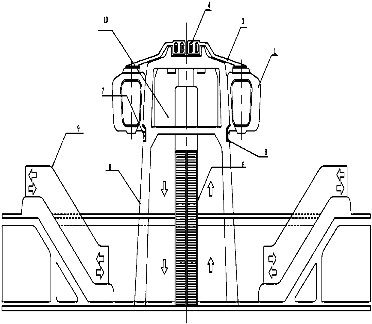
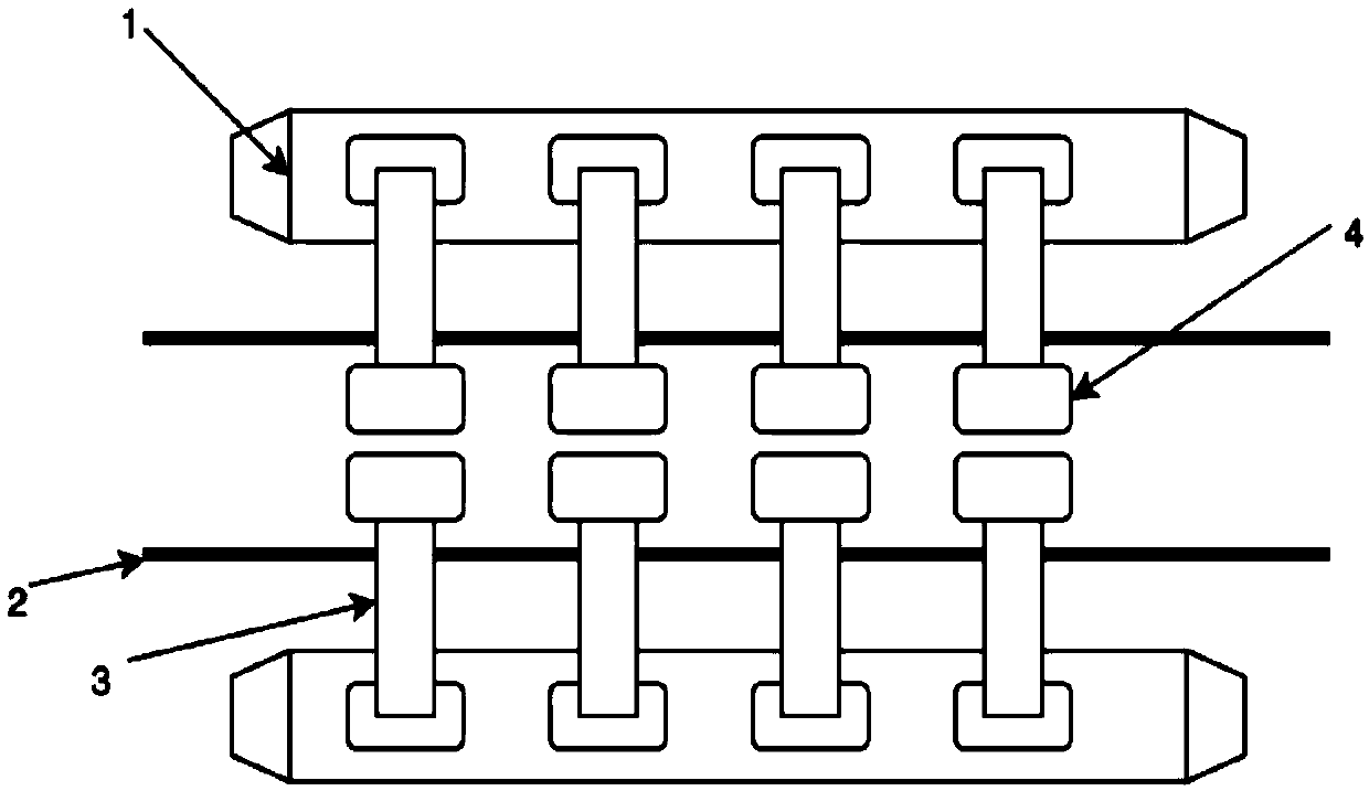
[0023] Such as figure 2 As shown, the present invention provides a rail vehicle suspension system, including a support body 6, a track 2 is arranged in the middle above the support body 6 to form a track layer, and a carriage 1 is provided on the side of the support body 6. The suspension system Including: a suspension assembly 3 fixed integrally with the carriage 1, one end of the suspension assembly 3 is fixedly connected to the carriage 1, the other end of the suspension assembly 3 is inserted into the track 2, and the carriage 1 is passed thro...


PUM


Abstract

The invention discloses a hanging system of a rail car, and belongs to the field of rail traffic. The hanging system comprises a supporting body. A rail is arranged above the supporting body, and a carriage is arranged on the side face of the supporting body. The hanging system further comprises a hanging assembly, one end of the hanging assembly is connected with a carriage box, the other end ofthe hanging assembly stretches into the rail, and the carriage is hung on one side of the rail. The hanging assembly comprises a hanging arm, a hanging part, a clamping part and a connecting part, wherein the hanging part is fixedly connected to the carriage body, the clamping part is clamped into the rail, and the connecting part is fixedly connected with a power drive device. In addition, a supporting structure for supporting the rail is provided with an inwards-concave auxiliary rail, and an auxiliary structure arranged on the carriage is clamped into an auxiliary rail. Traditional steel wire ropes or chains are replaced with the hanging system of the rail car, by the adoption of the mode that the hanging assembly is used for hanging and the side face auxiliary rail is used in cooperation, the carriage is supported and dragged, and the carriage runs along one side of the rail more stably.

Description

technical field [0001] The invention belongs to the field of rail transportation, and in particular relates to a rail vehicle suspension system. Background technique [0002] At present, the urban rail suspension device mainly adopts the following methods: using anti-off board, steel wire rope, chain, bolt assembly and other structures. Among them, the anti-off board needs to occupy a large installation space and has high requirements for the installation position, so it is not suitable for application in On rail vehicles, when steel wire ropes or chains are used, due to the relative movement between the car body and the horizontal beam, it is necessary for the steel wire ropes or chains to have a considerable margin. At this time, under certain conditions, they will sag and touch The horizontal beam will cause the horizontal beam to be worn and corroded, and even cause a fracture accident. The chassis equipment is directly hung on the lower surface of the chassis beam throu...

Claims


Application Information

Patent Timeline
Patent Type & Authority Applications(China)
IPC IPC(8): B61B3/02B61B1/00
Inventor 丁叁叁庞世俊姜良奎张恒志张琪
Owner CRRC QINGDAO SIFANG CO LTD
Learn More