
A heat pipe runner combined total heat recovery device and method

A total heat recovery, combined technology, applied in heat recovery system, heating method, energy recovery system for ventilation and heating, etc. The effect of improving sensible heat recovery efficiency, compact structure and easy control

Active Publication Date: 2020-02-04
中净鹏飞新能源科技有限公司
View PDF6 Cites 0 Cited by
  • Summary
  • Abstract
  • Description
  • Claims
  • Application Information

AI Technical Summary

Problems solved by technology

[0003] The rotary heat recovery device whose core material is made of non-combustible hygroscopic material or material with hygroscopic coating cannot transfer heat to the other side in time due to its large contact thermal resistance and the periodicity of heat recovery , so that the heat exchange efficiency is seriously affected, and the moisture exchange efficiency affected by the heat exchange is also affected
A heat pipe is a superconducting heat transfer element whose thermal conductivity exceeds that of any known metal. However, a heat pipe heat recovery device composed of a series of heat pipes can only recover the sensible heat of the air, not the latent heat of the air.

Method used


Image

  • A heat pipe runner combined total heat recovery device and method
  • A heat pipe runner combined total heat recovery device and method
  • A heat pipe runner combined total heat recovery device and method

Examples


Embodiment Construction

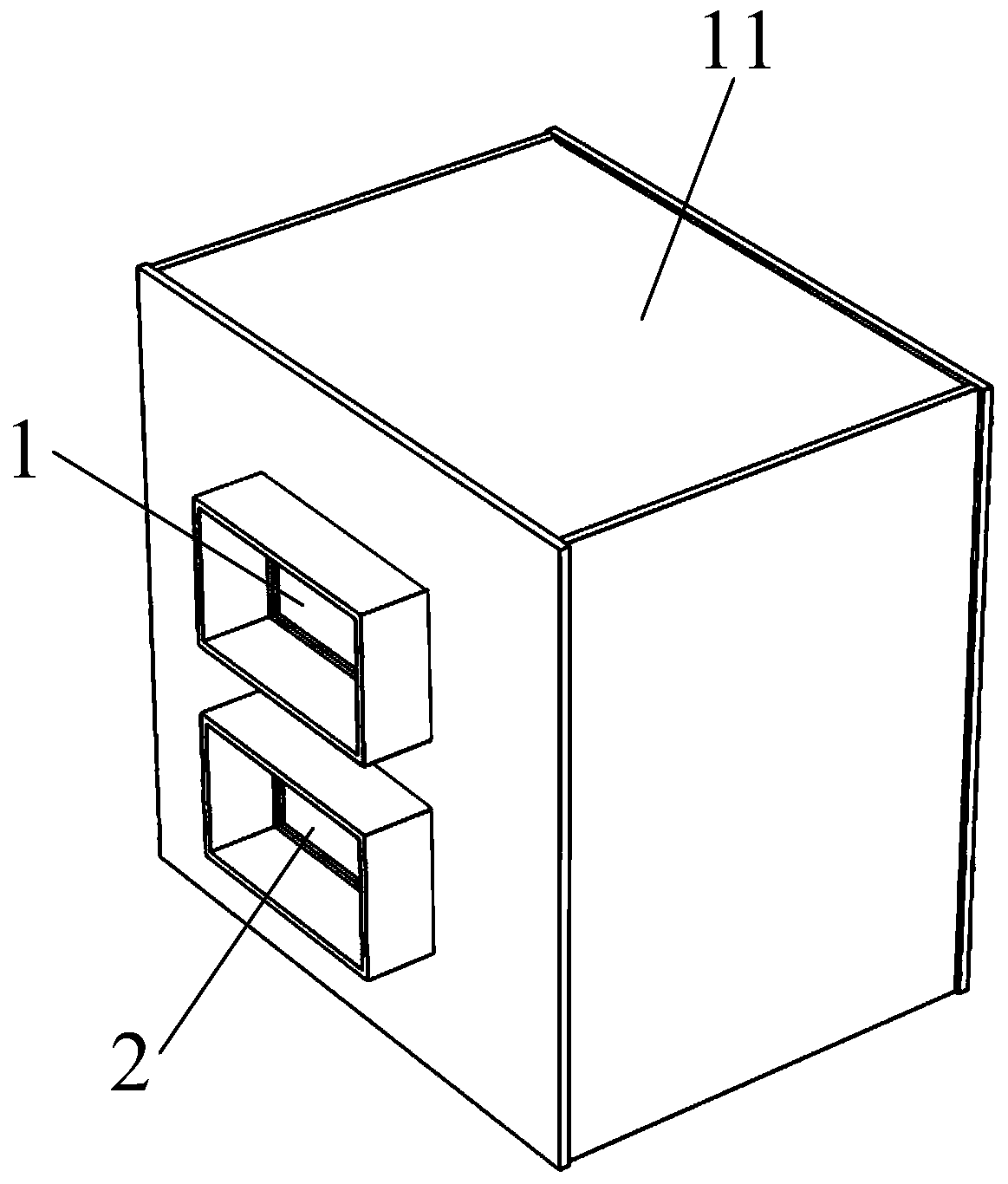
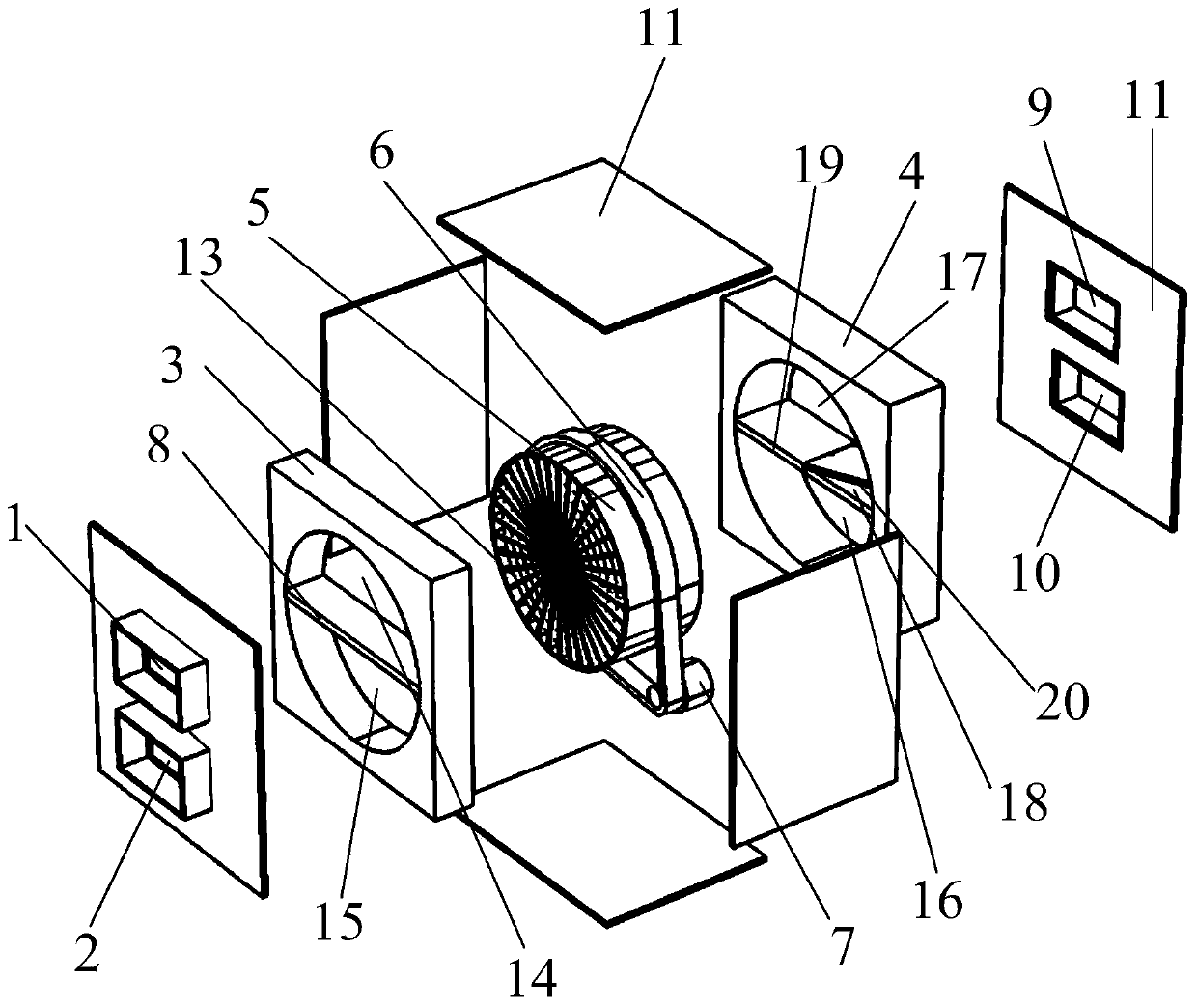
[0062] Such as Figure 1 to Figure 8 As shown, the heat pipe runner combined total heat recovery device of the present invention includes a casing 11, a front casing 3 arranged on the front side of the casing 11, a rear casing 4 arranged on the rear side of the casing 11, and a set The heat pipe runner assembly at the middle position in the box shell 11, the front casing 3 is provided with a fresh air inlet passage 14 and an exhaust air outlet passage 15, and the rear casing 4 is provided with a fresh air inlet passage 14 opposite to the The fresh air outlet channel 17 and the exhaust air inlet channel 16 arranged opposite to the exhaust air outlet channel 15, the front side wall of the box shell 11 is provided with a fresh air inlet 1 and an exhaust air outlet channel arranged opposite to the fresh air inlet channel 14 15 opposite to the exhaust air outlet 2, the rear side wall of the box shell 11 is provided with a fresh air outlet 9 opposite to the fresh air outlet channel ...


PUM


Abstract

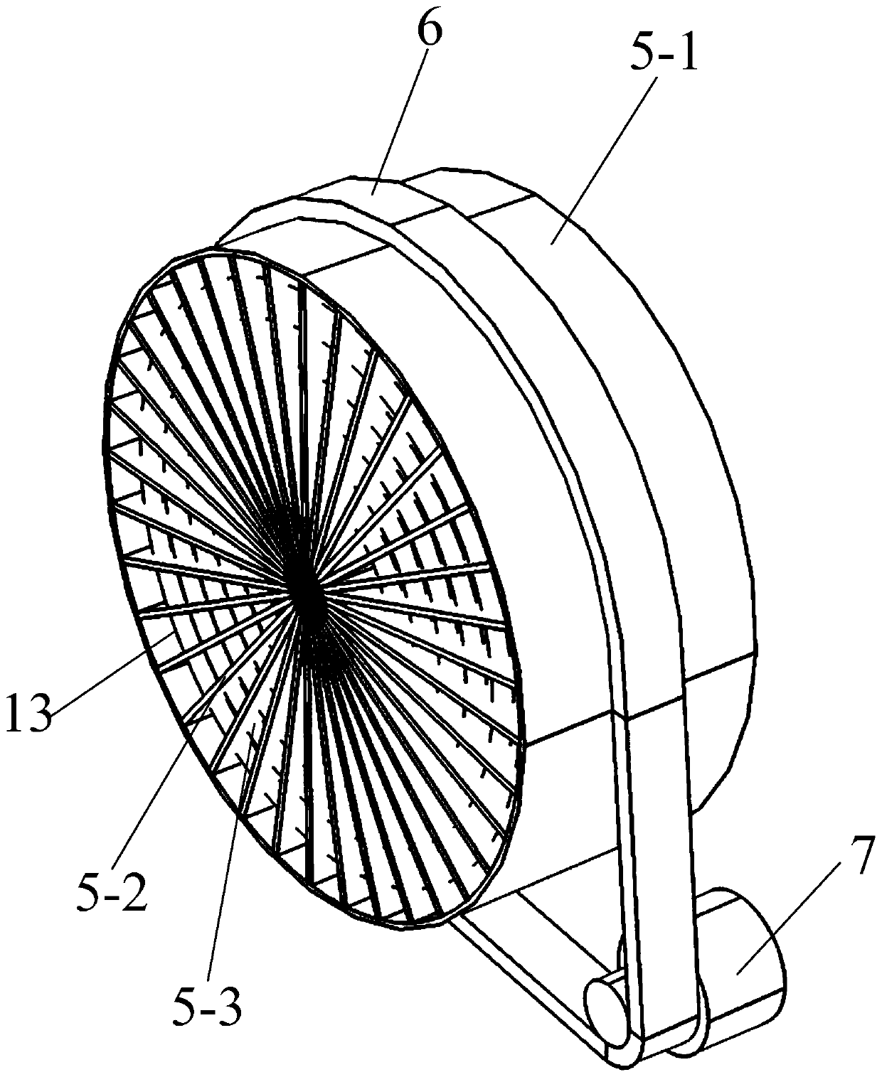
The invention discloses a heat pipe rotating wheel combined type total heat recovery device. The heat pipe rotating wheel combined type total heat recovery device comprises a case shell, a front shell, a rear shell and a heat pipe rotating wheel assembly, wherein a fresh air inlet channel and an exhaust air outlet channel are formed in the front shell, a fresh air outlet channel and an exhaust airinlet channel are formed in the rear shell, a fresh air inlet and an exhaust air outlet are formed in the front side wall of the case shell, and a fresh air outlet and an exhaust air inlet are formedin the rear side wall of the case shell; the heat pipe rotating wheel assembly comprises a rotating wheel, an annular heat pipe and a driving motor, wherein the rotating wheel comprises a wheel shelland a plurality of fins, and the fins divide the inner space of the wheel shell into a plurality of fin air channels; and a heat pipe dehumidifying material layer is arranged on the outer surface ofthe annular heat pipe, fin dehumidification material layers are arranged on the outer surfaces of the fins, and an output shaft of the driving motor is connected with a transmission belt which is bridged on the wheel shell. The invention further discloses a heat pipe rotating wheel combined type total heat recovery method. According to the heat pipe rotating wheel combined type total heat recoverydevice and the method, the heat exchange process is enhanced, the sensible heat recovery efficiency is improved and the total heat recovery under the working conditions in summer and winter can be achieved.

Description

technical field [0001] The invention belongs to the technical field of heat recovery, and in particular relates to a heat pipe runner combined total heat recovery device and method. Background technique [0002] Indoor air quality has become the focus of scholars' research in recent years, and indoor air quality has a great impact on people's life and work. Poor indoor air quality is directly linked to sick building syndrome, which can lead to a spike in illness, dizziness, fatigue, and reduced productivity. Factors affecting indoor air quality include: insufficient outdoor fresh air, air pollution from the building itself, air pollution from human activities, etc. Therefore, in order to improve indoor air quality, one of the most direct and effective measures is to ensure sufficient fresh air volume indoors. Set a specific fresh air volume for a specific environment, so that the indoor air quality meets the hygienic requirements. However, meeting the hygienic requirements...

Claims


Application Information

Patent Timeline
Patent Type & Authority Patents(China)
IPC IPC(8): F28D15/02F24F12/00F24F13/30
CPCF24F12/001F24F13/30F28D15/02Y02B30/56
Inventor 陈柳余卓雷刘异刘利李江波刘浪姬长发纪海维
Owner 中净鹏飞新能源科技有限公司
Learn More