Self-standing impact pressure resistance test device

A technology of impact withstand voltage and test equipment, which is applied in the direction of measuring equipment, measuring equipment casing, and testing dielectric strength, etc., which can solve the problems of uneven weight of the impact generator, inconvenient placement process, low test efficiency, etc., and achieve shortening The effect of test cycle, compact structure and convenient operation

Pending Publication Date: 2019-03-29
ELECTRIC POWER RESEARCH INSTITUTE OF STATE GRID NINGXIA ELECTRIC POWER COMPANY +1
View PDF0 Cites 4 Cited by
  • Summary
  • Abstract
  • Description
  • Claims
  • Application Information

AI Technical Summary

Problems solved by technology

Generally, the weight of this kind of impact generator is uneven, the placement pro

Method used


Image

  • Self-standing impact pressure resistance test device

Examples


Embodiment 1

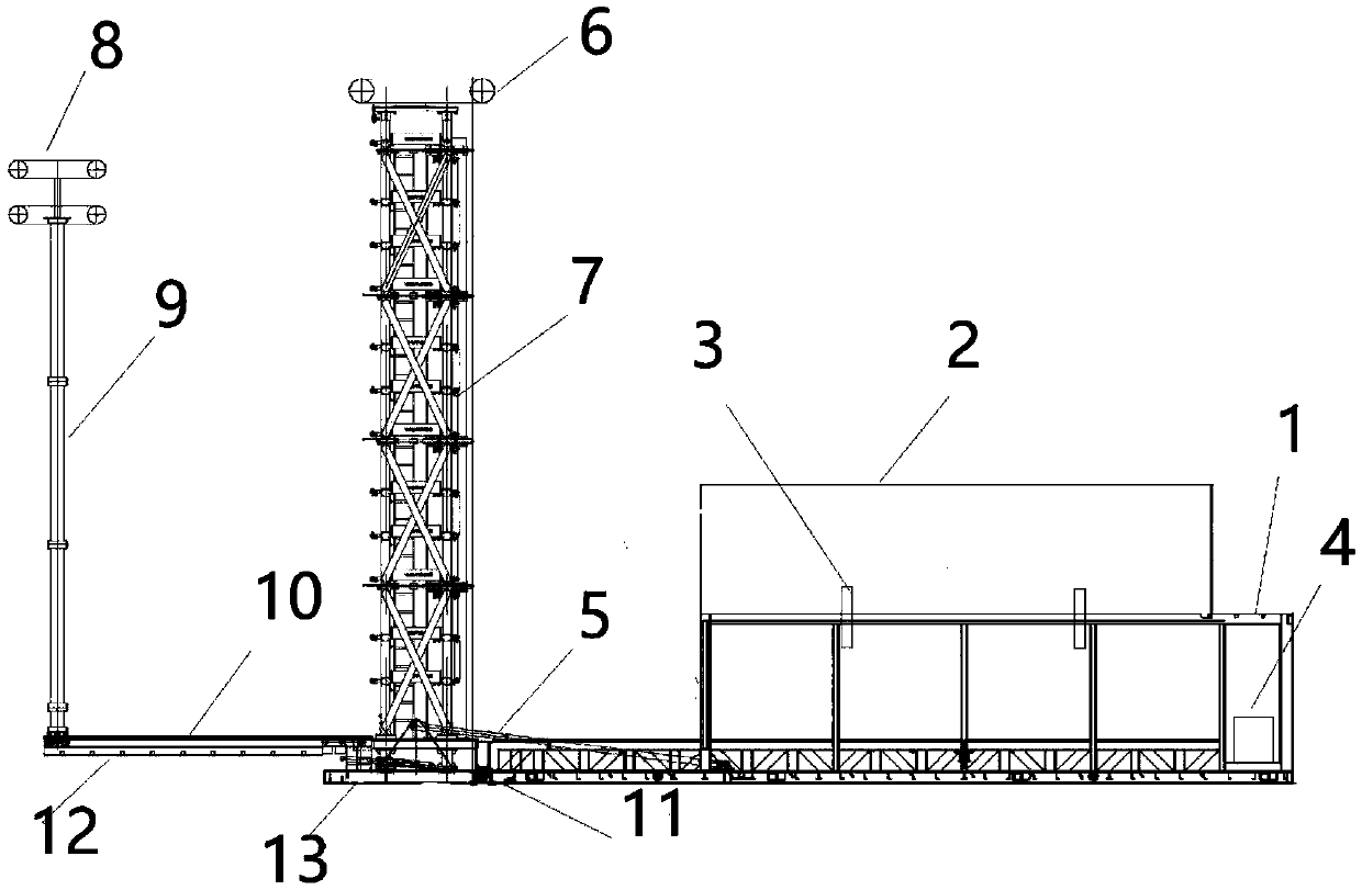
[0031] Such as figure 1 As shown, in this embodiment, a self-supporting impact pressure test device includes a container 1, a top cover 2, a rear cover plate 13, a top cover hydraulic ejector rod 3, a hydraulic rod 5, a hydraulic cylinder 13, and an impulse voltage generator Body 7, voltage divider 9, rail 10; the impulse voltage generator body 7 and voltage divider 9 are placed flat in the container 1, the rail 10 is hinged to the bottom end of the impulse voltage generator body 7, and the voltage divider 9 is slidably connected On the track 10, the container 1 includes a front cover, a rear cover 13, a bottom plate, side panels on both sides opposite to the bottom plate and a top cover 2, and one side of the front cover of the container 1, the rear cover 13 is hinged to the bottom plate One side of the top cover 2 of the container 1 is hinged to the top side of the container 1, and a top cover hydraulic jack 3 is provided between the side of the top cover 2 facing the contai...

Embodiment 2

[0033] Such as figure 1 As shown, the difference between this embodiment and Embodiment 1 is that the impulse voltage generator body 7 is composed of a plurality of insulating components, and the plurality of insulating components are stacked and connected to form a tower structure. The structure is mainly composed of four epoxy columns and an epoxy cylinder for installing discharge balls. The epoxy columns are made into one level every 770 mm according to the requirements of the impulse voltage generator, and two dry capacitors and resistors are installed on each level. and other components. Since the impulse voltage generator body equipment of the impulse voltage generator is placed horizontally in the container when stored, and vertically when used, in addition to the bottom support required for horizontal placement, the four main columns are subjected to huge bending moments and shear during the overturning process. Shearing force, the plurality of insulating components a...


PUM


Abstract

The invention discloses a self-standing impact pressure resistance test device. The self-standing impact pressure resistance test device is characterized in that: the device comprises a container, a top cover, a rear cover plate, a top cover hydraulic ejector rod, a hydraulic rod, a hydraulic cylinder, an impact voltage generator body, a voltage divider, and a rail; the impact voltage generator body and the voltage divider are disposed flat in the container; the rail is hinged to the bottom end of the impact voltage generator body, and the voltage divider is connected to the rail in a slidingway; one side edge of the top cover of the container is hinged to the side edge of the top of the container; the lower portion of the rear cover plate of the container is hinged to the bottom plate ofthe container; one end of the hydraulic rod is hinged to the inner side of the bottom plate of the container; and the other end of the hydraulic rod is hinged to a triangular support arranged on themiddle part of the rear cover plate. According to the self-standing impact pressure resistance test device, the structure is compact; the operation is convenient; the test period is greatly shortened;and the test efficiency is improved.

Description

technical field [0001] The invention relates to the technical field of high-pressure testing, in particular to a self-supporting impact pressure-resistant testing device. Background technique [0002] With the progress of society and rapid economic development, the requirements for the reliability and safety of power supply are getting higher and higher. The withstand voltage test is particularly important to ensure safe power supply. [0003] At present, on-site impact tests of electric power equipment such as GIS can accurately detect equipment failures for maintenance. Generally, such an impact generator has uneven counterweight, inconvenient placement process, long test period and low test efficiency. [0004] Impulse voltage generator equipment generates high voltage. The equipment components are composed of insulating materials and electrical components such as epoxy boards, epoxy tubes, dry capacitors, discharge balls, plate resistors, etc., and cannot be affected by...

Claims


Application Information

Patent Timeline
IPC IPC(8): G01R31/12G01R1/04
CPCG01R1/04G01R31/12G01R31/1254
Inventor 马云龙郭飞郝金鹏李秀广丁培吴旭涛周秀艾晓宇冯敬华马飞越田禄闫振华马波刘威峰李奇超倪辉
Owner ELECTRIC POWER RESEARCH INSTITUTE OF STATE GRID NINGXIA ELECTRIC POWER COMPANY
Why Eureka
Try Eureka