Heat exchanger and apparatus with heat exchanger

A technology of heat exchange device and heat dissipation device, which is applied in the fields of instruments, calculations, electrical digital data processing, etc., can solve problems such as noise generation, inability to discharge heat from peripheral computing chips, and limited heat dissipation effect, so as to avoid delay or damage, direct and effective Heat dissipation effect, the effect of improving the cooling effect

Inactive Publication Date: 2019-03-29
CASING MACRON TECH
View PDF8 Cites 0 Cited by
  • Summary
  • Abstract
  • Description
  • Claims
  • Application Information

AI Technical Summary

Problems solved by technology

[0006] If the heat dissipation mechanism is carried out in the form of the heat dissipation fan 44, the heat dissipation fan 44 and the exhaust fan 64 need to keep running during the power-on process of the host unit 60 in order to produce a good heat dissipation effect. Exhaust fan 64 can consume a large amount of electric power, and the operation of this cooling fan 44 and this exhaust fan 64 also can produce noise simultaneously, and after using for a long time, the temperature of this central processing unit 51 and this graphics processing unit 62 can raise; In addition, The heat dissipation fan 44 generates the flow of air to take away the heat. The heat dissipation fan 44 installed on the central processing unit 51 and the graphics processor 62 cannot directly perform an effective heat dissipation on the peripheral computing chip, so the overall heat dissipation effect is limited.

Method used


Image

  • Heat exchanger and apparatus with heat exchanger
  • Heat exchanger and apparatus with heat exchanger
  • Heat exchanger and apparatus with heat exchanger

Examples


Embodiment Construction

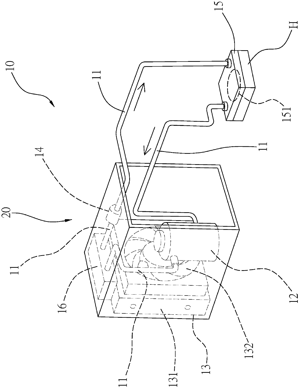
[0065] see image 3 As shown, it is a three-dimensional appearance view of the heat exchange device of the present invention. The so-called "heat exchange" refers to the ability to exchange heat and cold. The heat exchange device 10 includes: a pipeline unit 11, which can be filled with There is a heat-transfer medium (not shown in the figure), and the heat-transfer medium is a substance capable of transitioning between gaseous and liquid states, such as refrigerant or water.

[0066] A steam or gas pressurizer 12, the steam or gas pressurizer 12 is connected with the pipeline unit 11, the steam or gas pressurizer 12 can compress the heat transfer medium in the pipeline unit 11 to high temperature and high pressure gaseous state; the vapor or gas pressurizer 12 may be a compressor.

[0067] A heat dissipation device 13, the heat dissipation device 13 is connected with the pipeline unit 11, and connected behind the steam or gas pressurizer 12, that is, the steam or gas pressur...


PUM


Abstract

A heat exchanger and an apparatus having the same are disclosed. A heat transfer medium is filled in a pipe unit; the heat transfer medium flows to a heat absorber through the circulation of a vapor or gas pressurizer, a heat dissipation device and a throttling device. The heat absorber is provided with a heat absorbing surface which can contact with a heat source, and the heat transfer medium flowing through the heat absorber will take away the heat of the heat source through the heat absorbing surface. Moreover, the heat exchange device can be arranged in an apparatus, the apparatus has at least one power supply unit and at least one working unit, the working unit can form the heat source when the working unit is operated, the working unit contacts with the heat absorbing surface of theheat absorber, directly performs heat absorption action and can carry out an effective heat exchange cycle to achieve the heat dissipation effect.

Description

technical field [0001] The present invention relates to a heat exchanging device, which is applicable to equipment with the heat exchanging device, such as heat dissipation of a computer mainframe, but the equipment with the heat exchanging device is not limited to be applied only to the computer mainframe. Background technique [0002] Press, the early heat dissipation system, such as the heat dissipation system installed on a CPU (central processing unit, central processing unit) of a computer and other heat sources on a chip, is usually equipped with a fin with heat dissipation and heat conduction functions on the top. fins (or heat dissipation fins), through which the heat source is guided out to complete a heat dissipation process, but the advancement of technology has reduced the contact area of ​​the heat source, and the increase in the instruction cycle has further caused the entire heat source to generate heat In addition to the poor efficiency, because the main cas...

Claims


Application Information

Patent Timeline
Patent Type & Authority Applications(China)
IPC IPC(8): G06F1/20
CPCG06F1/20
Inventor 萧奕彰
Owner CASING MACRON TECH
Why Eureka
Try Eureka