
Land use change simulation method and system

A simulation method and land technology, applied in design optimization/simulation, special data processing applications, instruments, etc., can solve problems such as reducing simulation accuracy, and achieve the effect of enhancing applicability and enhancing simulation accuracy

Active Publication Date: 2019-03-29
SOUTH CHINA AGRI UNIV
View PDF4 Cites 2 Cited by
  • Summary
  • Abstract
  • Description
  • Claims
  • Application Information

AI Technical Summary

Problems solved by technology

[0004] The CLUE-S model generally includes two aspects: top-down macro control and bottom-up micro rules; however, under the operating mechanism of this CLUE-S model, less consideration is given to spatial differences on the regional scale. From the perspective of its simulation process, the CLUE-S model focuses on simulating land use change from a macro perspective, and believes that the study area is homogeneous, which is consistent with the objective spatial differences in natural and human factors in geographical areas. Paradoxically, the impact of driving factors on land use change in different spatial divisions is different, and using a unified driving force regression equation to drive the process of land use change with spatial differences reduces the accuracy of the simulation; geographical weighting The regression (Geographically Weighted Regression, GWR) model allows local parameters to be used for function fitting. Using the GWR model to integrate land use suitability equations with different regional characteristics can make the model better solve the problem of spatial heterogeneity of driving factors; On the basis of some land use change simulation models, the concept of spatial partition is introduced to apply to the simulation of regions with macroscopic spatial partition differences

Method used


Image

  • Land use change simulation method and system
  • Land use change simulation method and system
  • Land use change simulation method and system

Examples


Embodiment

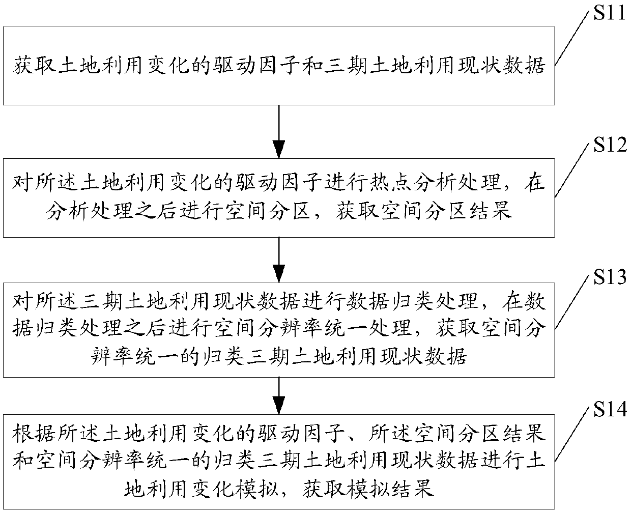
[0049] see figure 1 , figure 1 is a schematic flow chart of the land use change simulation method in the embodiment of the present invention.

[0050] Such as figure 1 As shown, a land use change simulation method based on the zonal CLUE-S model, the method includes:

[0051] S11: Obtain the driving factors of land use change and the data on the current status of land use in the three periods;

[0052] In the specific implementation process of the present invention, the driving factors of the land use change include natural resource condition factors and socioeconomic condition factors; wherein, the natural resource condition factors include vegetation index factors, water body index factors and agricultural suitability index factors; The socio-economic condition factors include the distance factor from the county center, the distance factor from the expressway and the distance factor from the provincial road.

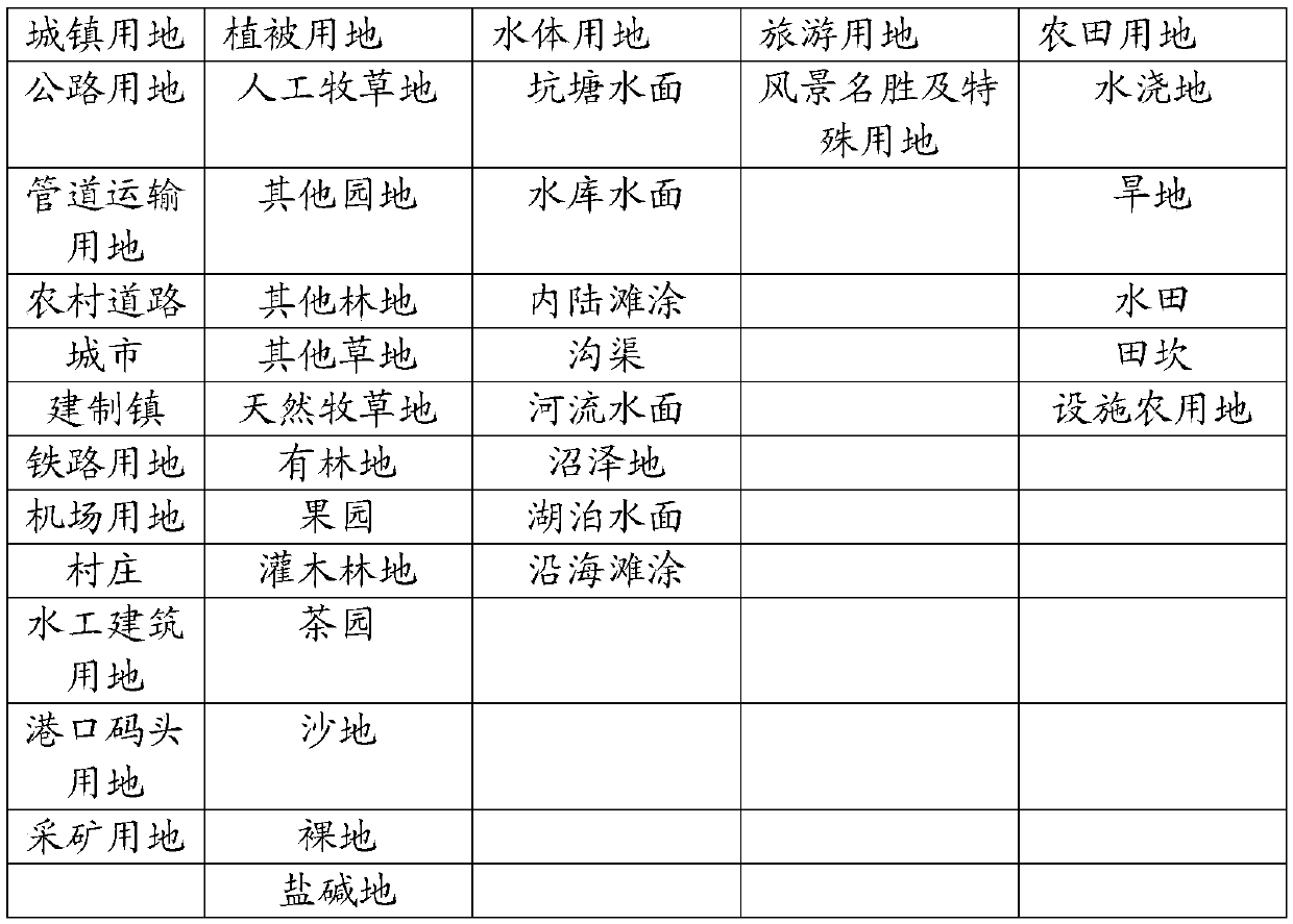
[0053] The current land use data of the three phases include ...


PUM


Abstract

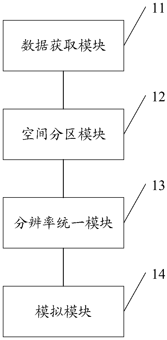
The invention discloses a land use change simulation method and system based on a partitioned CLUE-S model. The method comprises the following steps: obtaining driving factors of land use change and three-phase land use status data; The driving factors of the land use change are analyzed and processed by hot spots, and after the analysis and processing, the spatial partition is carried out to obtain the spatial partition result; carrying out data classification and processing on the three-phase land use status data, uniformly processing the spatial resolution after the data classification andprocessing, and obtaining the three-phase land use status data with unified spatial resolution; according to the driving factors of the land use change, the land use change simulation is carried out according to the classified land use status data of three periods with unified spatial zoning results and spatial resolution, and the simulation results are obtained. In the implementation of the invention, the regional difference of land use in space can be reflected, the applicability of the research area with obvious regional difference and the precision of the simulation can be realized.

Description

technical field [0001] The present invention relates to the technical field of land use change simulation, in particular to a land use change simulation method and system based on a zonal CLUE-S model. Background technique [0002] The research content of Land Use / Cover Change (LUCC) includes many aspects such as the process of land use and land cover change, the driving mechanism, and the impact of resources, ecology and environmental effects. Land use change simulation is one of the core contents of LUCC; in recent years, large-scale land use change simulation has received more attention, how to consider regional spatial differences and improve simulation quality has become a technology that needs to be considered in the process of large-scale simulation question. [0003] According to recent studies on the driving force, structure, and model of land use change by scholars, it is found that due to the influence of location conditions, natural conditions, or administrative...

Claims


Application Information

Patent Timeline
IPC IPC(8): G06F17/50
CPCG06F30/20
Inventor 胡明月崔学森刘轶伦郭玉彬隆少秋黎世勇
Owner SOUTH CHINA AGRI UNIV
Learn More