A method for predicting shrinkage cavity closure during continuous casting billet reduction process

A calculation method and continuous casting billet technology, applied in the direction of calculation, design optimization/simulation, special data processing application, etc., to achieve the effect of enriching the theoretical system

Active Publication Date: 2019-03-29
NORTHEASTERN UNIV
View PDF9 Cites 2 Cited by
  • Summary
  • Abstract
  • Description
  • Claims
  • Application Information

AI Technical Summary

Problems solved by technology

At present, there are many technical patents related to the reduction process and equipment design, but there are few reports on the quantitative calculation method of the shrinkage cavity closure degree of the slab during the reduction process

Method used


Image

  • A method for predicting shrinkage cavity closure during continuous casting billet reduction process
  • A method for predicting shrinkage cavity closure during continuous casting billet reduction process
  • A method for predicting shrinkage cavity closure during continuous casting billet reduction process

Examples


Embodiment 1

[0028] Example 1 Prediction of shrinkage cavity closure during slab reduction:

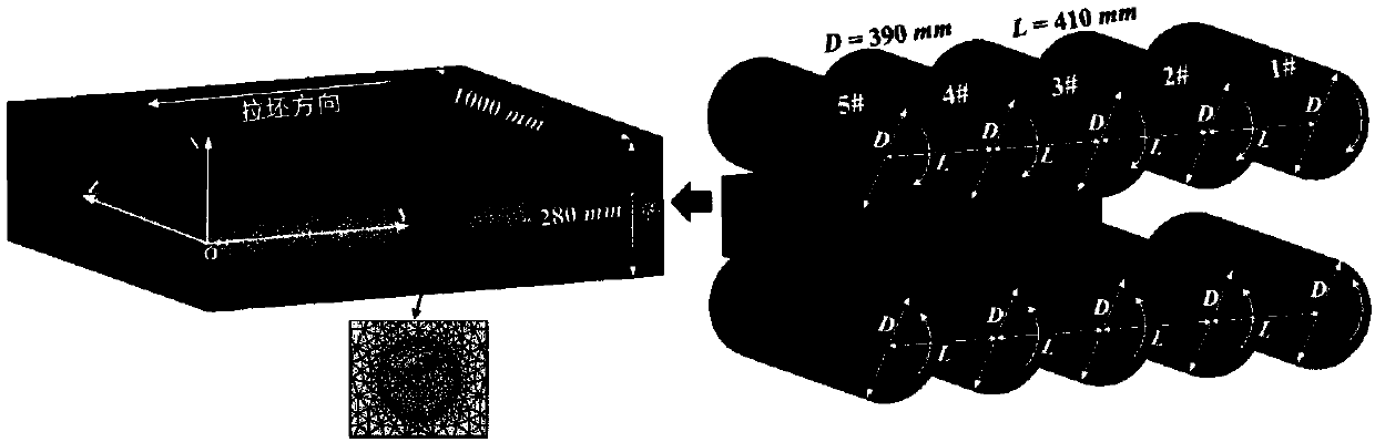
[0029] figure 1 The three-dimensional finite element model of the slab pressing process established for this example. In this example, the slab has a thickness of 280mm and a width of 2000mm. The slab pressing process is completed by sector sections, and each sector section contains 5 pairs of casting rolls (corresponding to figure 1 1#-5# in ), the diameter (D) of each pressing roller is 390mm, and the distance between rollers (L) in the casting direction is 410mm. According to the actual casting speed, the rotational speed of each casting roller in this example is set to 0.8 m / min. Since half of the width of the slab pressing process is selected to establish a three-dimensional finite element model, the attached figure 1 The cross-sectional dimension of the cast slab is 280mm (thickness) × 1000mm (half the width). The slab in the finite element model is divided by tetrahedral mesh, and the ...

Embodiment 2

[0032] Example 2 Prediction of shrinkage cavity closure during the reduction process of rectangular billet:

[0033] attached Figure 5 This is the three-dimensional finite element model of the rectangular billet pressing process established for this example. In this example, the rectangular blank has a thickness of 320mm and a width of 410mm. The reduction process of the rectangular billet is completed by the tension leveler. Each tension leveler contains 2 pairs of casting rolls, and the diameter of each roll down is 500mm. According to the actual casting speed, the rotation speed of each casting roll in this example is set to 0.42m / min. Since half of the width of the rectangular billet is selected to establish a three-dimensional finite element model, the attached Figure 5 The cross-sectional dimension of the cast slab is 320mm (thickness) × 212.5mm (half the width). The slab in the finite element model is divided by tetrahedral mesh, and the mesh size is about 10mm. ...


PUM


Abstract

The invention belongs to the field of continuous casting production in the iron and steel metallurgy industry, in particular to a method for predicting shrinkage cavity closure degree of continuous casting billet (including slab and rectangular billet) during reduction process. A 3-D finite element simulation model of continuous casting billet reduction process is established, Equivalent-effect strain at each position in that reduction process can be calculate and determined, and the shrinkage cavity closure degree prediction method based on the equivalent-effect strain proposed by the invention can realize high-efficiency and accurate prediction of the shrinkage cavity closure degree in the reduction process of the casting billet, thereby providing quantitative key data support for the development of the reduction process and related equipment. The calculated results of the preset degree of shrinkage cavity closure and the predict formula of the degree of shrinkage cavity closure arein good agreement with each other, and the accuracy and applicability of the predicting method of the degree of shrinkage cavity closure proposed by the invention are proved.

Description

technical field [0001] The invention belongs to the field of continuous casting production in the iron and steel metallurgical industry, and in particular relates to a method for predicting the closing degree of shrinkage cavities during the reduction process of continuous casting slabs (including slabs and rectangular slabs). Background technique [0002] The shrinkage cavity and porosity in the center of the continuous casting slab are internal quality defects that often occur in the continuous casting process, and this defect is one of the main factors affecting the mechanical properties of the final rolled product. At present, the solidification end reduction technology is one of the most effective technical means to effectively improve the shrinkage cavity, porosity and other internal quality defects of the continuous casting slab. This technology takes advantage of the natural temperature gradient at the end of the solidification of the cast strand, and can effectively...

Claims


Application Information

Patent Timeline
Patent Type & Authority Applications(China)
IPC IPC(8): G06F17/50B22D11/16
CPCB22D11/16G06F30/23Y02P90/30
Inventor 祭程吴晨辉朱苗勇
Owner NORTHEASTERN UNIV
Why Eureka
Try Eureka