
High-frequency low-loss data transmission line

A data transmission line, low-loss technology, applied in conductors, insulated cables, electrical components, etc., can solve problems such as the inability to guarantee the stable and effective transmission of 5G network signals, unsuitable for 5G network data transmission, and high-frequency signal attenuation. Stable and effective transmission, strong protection, reducing attenuation effect

Pending Publication Date: 2019-03-29
深圳讯诺科技有限公司
View PDF0 Cites 2 Cited by
  • Summary
  • Abstract
  • Description
  • Claims
  • Application Information

AI Technical Summary

Problems solved by technology

However, the data transmission lines in the current technology have serious attenuation of high-frequency signals in the high frequency band of 3.5GHz-30GHz or even higher, and are not suitable for realizing data transmission in the 5G network. In addition, the insulating layer structure of the data transmission lines in the prior art is generally , poor high temperature resistance, not suitable for 5G network data transmission, cannot guarantee the stable and effective transmission of 5G network signals

Method used


Image

  • High-frequency low-loss data transmission line
  • High-frequency low-loss data transmission line
  • High-frequency low-loss data transmission line

Examples


Embodiment 1

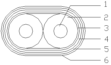
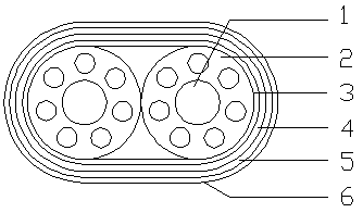
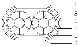
[0028] Such as figure 1 , figure 2 and image 3 As shown, a high-frequency low-loss data transmission line includes an inner conductor 1, a first insulating layer 2, a second insulating layer 3, a first shielding layer 4, a second shielding layer 5 and an outer layer 6; the first The insulating layer 2 covers the inner conductor 1, the second insulating layer 3 covers the first insulating layer 2, the first shielding layer 4 covers the second insulating layer 3, the The second shielding layer 5 wraps outside the first shielding layer 4 , and the outer coating layer 6 wraps outside the second shielding layer 5 .

[0029] Such as figure 1 , figure 2 and image 3 As shown, the inner conductor 1 is used to conduct current, and the corresponding conductor specification is selected according to the required strength; the number of the inner conductor 1 is two, and the two inner conductors 1 are separately coated with the first insulation Layer 2, the second insulating layer ...

Embodiment 2

[0034] Such as Figure 4 , Figure 5 and Figure 6 As shown, a high-frequency low-loss data transmission line is characterized in that it includes an inner conductor 1, a first insulating layer 2, a second insulating layer 3, a first shielding layer 4, an inner layer 7, a second shielding layer 5 and Outer coating layer 6; the first insulating layer 2 is wrapped outside the inner conductor 1, the second insulating layer 3 is wrapped outside the first insulating layer 2, and the first shielding layer 4 is wrapped around the second Outside the two insulating layers 3, the inner coating layer 7 is wrapped outside the first shielding layer 4, the second shielding layer 5 is wrapped outside the inner coating layer 7, and the outer coating layer 6 is wrapped outside the first shielding layer 4. Outside the second shielding layer 5.

[0035] Such as Figure 4 , Figure 5 and Figure 6 As shown, the inner conductor 1 is used to conduct current, and the corresponding conductor sp...


PUM

PropertyMeasurementUnit
Diameteraaaaaaaaaa
Thicknessaaaaaaaaaa
Thicknessaaaaaaaaaa

Abstract

The invention discloses a high-frequency low-loss data transmission line. One technical scheme is that the transmission line comprises an internal conductor, a first insulating layer, a second insulating layer, a first shielding layer, a second shielding layer, and an outer sheath. The internal conductor is wrapped by the first insulating layer, and the first insulating layer is wrapped by the second insulating layer. The second insulating layer is wrapped by the first shielding layer, and the first shielding layer is wrapped by the second shielding layer. The second shielding layer is wrappedby the outer sheath. The transmission line reduces the attenuation of a high-frequency signal, is good in high temperature resistance, and can guarantee the stable and effective transmission of a 5Gnetwork data signal.

Description

technical field [0001] The invention relates to the technical field of communication wires, in particular to a high-frequency and low-loss data transmission line. Background technique [0002] 5G network is the fifth generation of mobile communication network, 5G wireless key technologies: micro base station and Massive MIMO. [0003] The capacity of 5G is 1000 times that of 4G, and the peak rate is 10Gbps-20Gbps. There are three tricks to improve capacity and rate: spectrum bandwidth, spectrum efficiency and the number of cells. [0004] Spectrum bandwidth, high-frequency frequency resources are abundant, and at the same time, the current low-frequency band less than 3GHz is basically occupied by 2 / 3 / 4G networks, so the 5G network has to expand to the high-frequency band 3.5GHz-30GHz (or even higher). Micro base stations have become the key to solving network coverage and capacity in the future. In the future, various street facilities such as street lamps, billboards, an...

Claims


Application Information

Patent Timeline
IPC IPC(8): H01B7/22H01B7/18H01B7/02H01B7/08
CPCH01B7/0258H01B7/0807H01B7/0823H01B7/0861H01B7/1875H01B7/225
Inventor 孔浩查阳贾利宾易涛于国庆桂宏兵
Owner 深圳讯诺科技有限公司
Learn More