Die cutting device for conductive cloth indentation lines

A technology of indentation line and conductive cloth, applied in the field of conductive cloth, can solve the problems of fast rebound, poor holding force of indentation line, disappearance, etc., and achieve the effect of fast rebound speed, good toughness and easy processing and manufacturing.

Pending Publication Date: 2019-03-29
上海昊佰智造精密电子股份有限公司
View PDF7 Cites 1 Cited by
  • Summary
  • Abstract
  • Description
  • Claims
  • Application Information

AI Technical Summary

Problems solved by technology

However, although this type of device can die-cut the indentation line on the conductive cloth, the retention force of the indentation line is poor and the rebound is fast. Generally, after 24 hours of storage, the imprint of the indentation line will be significantly weakened. Even disappear, seriously affecting the normal use of conductive cloth

Method used


Image

  • Die cutting device for conductive cloth indentation lines
  • Die cutting device for conductive cloth indentation lines
  • Die cutting device for conductive cloth indentation lines

Examples


Embodiment 1

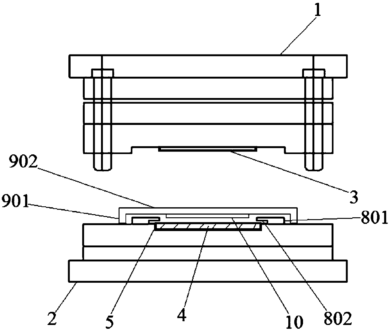
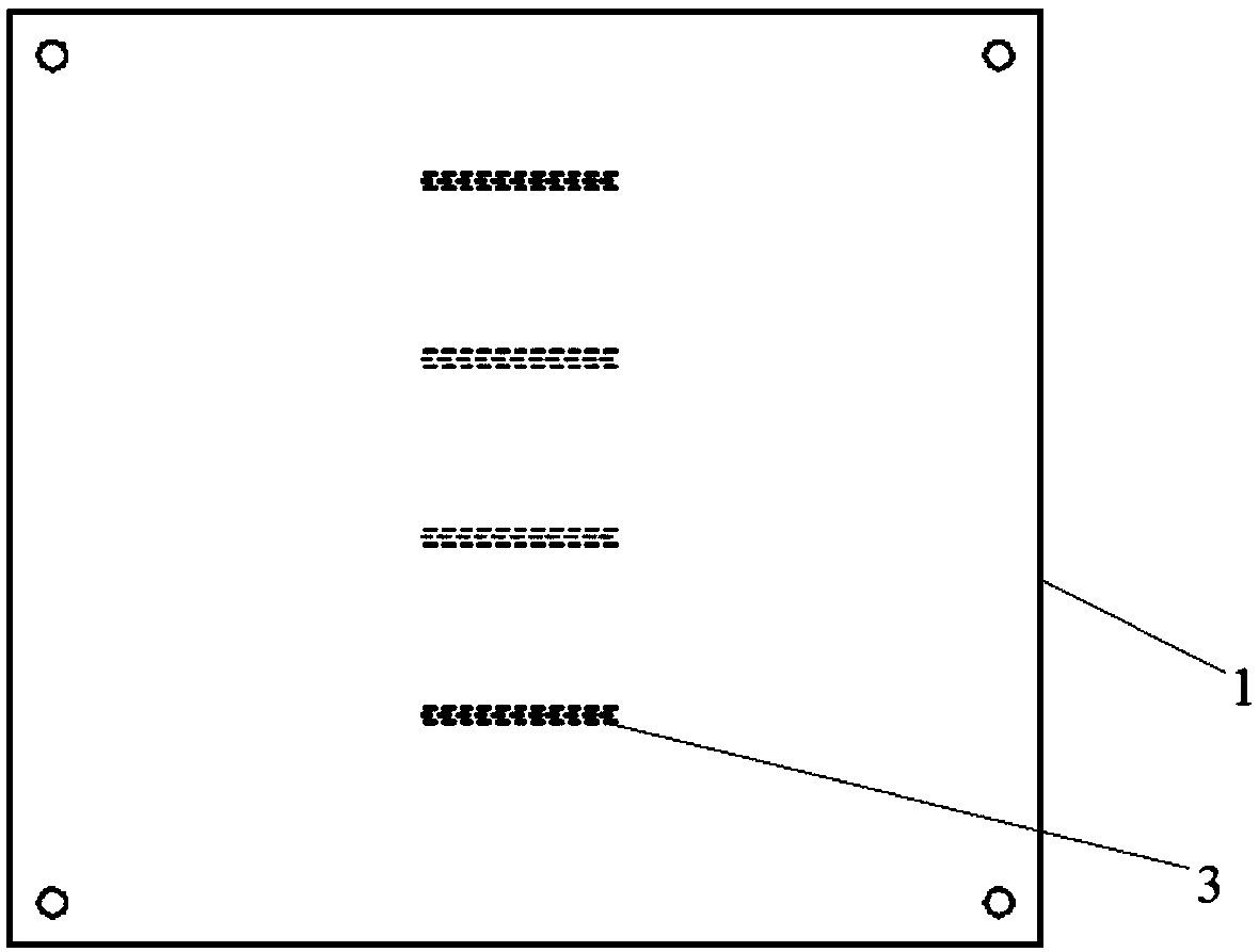
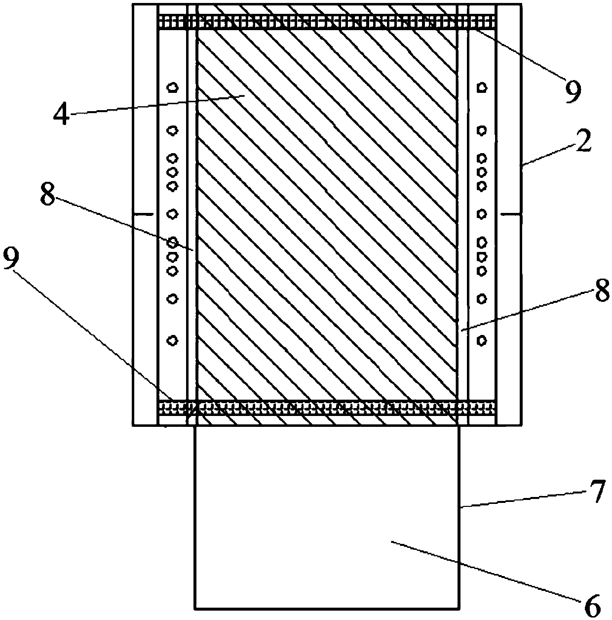
[0031] Such as figure 1 Shown is a die-cutting device for conductive cloth creasing lines, which is used for die-cutting creasing lines on conductive cloth belts. The lower mold base 2 that matches the base 1, such as figure 2 As shown, the lower surface of the upper mold base 1 is provided with an indentation line die cutter 3, and the lower mold base 2 is provided with a silicone pad 4 compatible with the indentation line die cutter 3 and a conductive fabric belt. The blocking mechanism.

[0032] Wherein, the silicone pad 4 is located directly below the die cutter 3 on the creasing line. The lower mold base 2 is provided with a silica gel pad installation groove 5 compatible with the silica gel pad 4, and the silica gel pad 4 is located in the silica gel pad installation groove 5. The depth of the silica gel pad installation groove 5 is 0.7mm, and the thickness of the silica gel pad 4 is 0.7mm.

[0033] The conductive fabric belt includes a conductive fabric belt main b...

Embodiment 2

[0039] In this embodiment, the depth of the installation groove 5 of the silica gel pad is 0.5 mm, the thickness of the silica gel pad 4 is 0.9 mm, and the rest are the same as in Embodiment 1.

Embodiment 3

[0041] In this embodiment, the depth of the installation groove 5 of the silica gel pad is 0.6 mm, the thickness of the silica gel pad 4 is 0.8 mm, and the rest are the same as in Embodiment 1.


PUM

PropertyMeasurementUnit
depthaaaaaaaaaa
thicknessaaaaaaaaaa
depthaaaaaaaaaa

Abstract

The invention relates to a die cutting device for conductive cloth indentation lines. The die cutting device is used for carrying out die cutting on indentation lines on a conductive cloth material strip, and comprises an upper die base and a lower die base which is arranged below the upper die base and matched with the upper die base. The lower surface of the upper die base is provided with an indentation line cutter, and the lower die base is provided with a silicone pad matched with the indentation line cutter and a material blocking mechanism matched with the conductive cloth material strip. Compared with the prior art, through arranging the silicone pad on the lower die base, the conductive cloth material strip and the indentation line cutter are supported flexibly from below, the indentation line cutter is ensured to be capable of being pressed into the conductive cloth material strip completely, so that the depth of the indentation lines is obvious, the compactness is good, therebound speed is slow, the imprint is not prone to recede and disappear, the retention is good, and the conductive cloth material strip can be effectively prevented from being lifted by the indentation line die cutter, thereby ensuring the normal proceeding of the continuous die cutting process.

Description

technical field [0001] The invention belongs to the technical field of conductive cloth, and relates to a die-cutting device for creasing lines of conductive cloth. Background technique [0002] Conductive cloth is woven from nylon or polyester fibers coated with metals such as copper and nickel on the surface. It has extremely high conductivity and shielding efficiency, and has anti-oxidation and anti-corrosion properties. It is ideal for shielding various electronic products. Material. When conductive cloth is used, it is often necessary to wrap it outside the component. Since the inside of the bent conductive cloth has an elastic bending tension to restore it to its original shape, when the bending tension inside the conductive cloth is greater than the adhesive force between the two layers of conductive cloth that are bonded to each other, the conductive cloth is easy to spread out. Leave the adhesive side of the conductive cloth exposed. In order to release the bendi...

Claims


Application Information

Patent Timeline
Patent Type & Authority Applications(China)
IPC IPC(8): H01B13/00
CPCH01B13/0009H01B13/0026H01B13/0036
Inventor 蒋建国张涛
Owner 上海昊佰智造精密电子股份有限公司
Why Eureka
Try Eureka