
cmos integrated process bjt structure and its manufacturing method

A manufacturing method and process technology, applied in the field of CMOS integrated process BJT structure, CMOS integrated process BJT manufacturing, can solve the problems of improvement limitation of divot process uniformity of height difference between AA and STI area, difficult control of divot process uniformity, etc., to achieve Improve the uniformity of current gain, improve the distribution of data, and increase the effect of current gain

Active Publication Date: 2022-05-27
SHANGHAI HUALI INTEGRATED CIRCUTE MFG CO LTD
View PDF0 Cites 0 Cited by
  • Summary
  • Abstract
  • Description
  • Claims
  • Application Information

AI Technical Summary

Problems solved by technology

The experimental results show that the height difference between the AA and STI regions and the uniformity of the divot process are quite difficult to control, and the height difference must be within a certain range to maintain the best performance of the MOS device, so the height difference between the AA and STI regions and the uniformity of the divot process are improved. has been severely restricted

Method used


Image

  • cmos integrated process bjt structure and its manufacturing method
  • cmos integrated process bjt structure and its manufacturing method
  • cmos integrated process bjt structure and its manufacturing method

Examples


Embodiment Construction

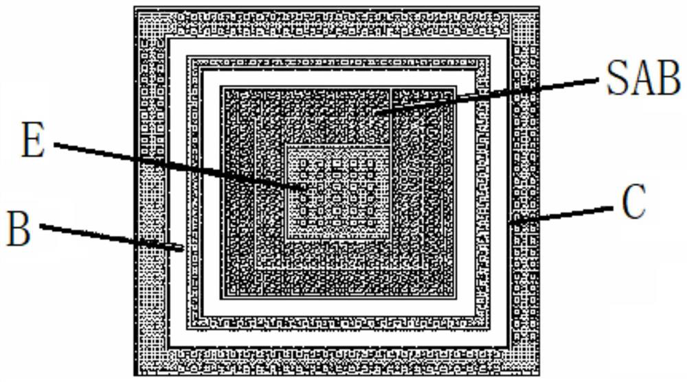
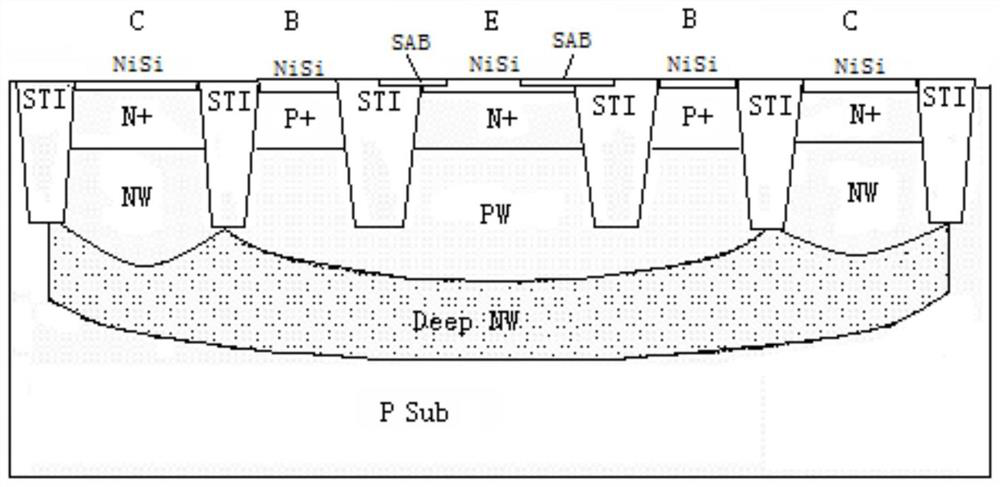
[0074] The first embodiment of the BJT structure of the CMOS integration process provided by the present invention includes: P well and N well arranged in parallel on a silicon substrate, a first shallow trench isolation is formed at the critical position of the P well and the N well, and a first shallow trench is formed in the P well There is a second shallow trench isolation, a first P+ doped region is formed in the P well between the first shallow trench isolation and the second shallow trench isolation, and a first P+ doped region is formed in the N well beside the first shallow trench isolation The first N+ doped region, the second N+ doped region is formed in the P well on the other side of the second shallow trench isolation, the second N+ doped region is formed with a parallel first electrode and a barrier layer, the first P+ A second electrode is formed on the doped region, and a third electrode is formed on the first N+ doped region; wherein, a flat layer is deposited...


PUM

PropertyMeasurementUnit
thicknessaaaaaaaaaa
thicknessaaaaaaaaaa

Abstract

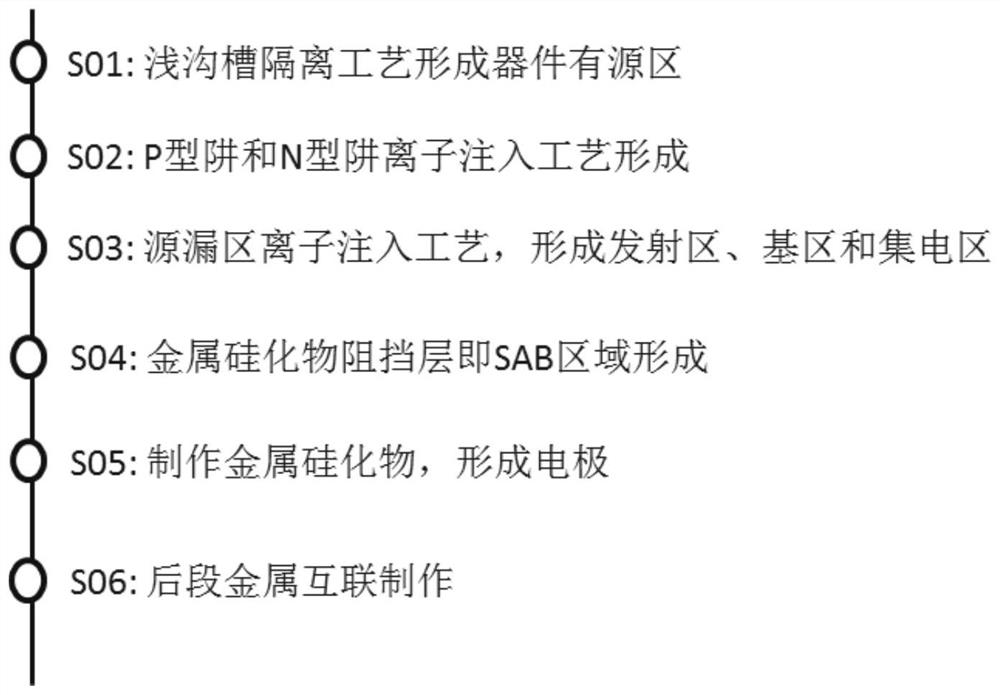
The invention discloses a CMOS integrated process BJT structure, which comprises: P wells and N wells arranged side by side on a silicon substrate, a first shallow trench isolation is formed at the boundary between the P well and N well, and a first shallow trench isolation is formed in the P well. Two shallow trench isolations, a first P+ doped region is formed in the P well between the first and second shallow trench isolations, and a first N+ doped region is formed in the N well next to the first shallow trench isolation , a second N+ doped region is formed in the P well on the other side of the second shallow trench isolation, and a parallel first electrode and a metal silicide barrier layer are formed on the second N+ doped region, and the first P+ doped region A second electrode is formed on the first N+ doped region, and a third electrode is formed on the first N+ doped region; before the source-drain region ion implantation process, a flat layer is deposited, source-drain region ion implantation is performed, a metal silicide barrier layer is deposited, and metal silicide is performed. The blocking layer is etched to form the first electrode to the third electrode. The invention also discloses a BJT manufacturing method of CMOS integration technology. The invention can improve the uniformity of the current gain of the transistor, and can realize precise adjustment of the current gain.

Description

technical field [0001] The invention relates to the field of semiconductors, in particular to a CMOS integrated process BJT structure. The invention also relates to a CMOS integrated process BJT manufacturing method. Background technique [0002] No matter in the field of digital or analog integrated circuits, CMOS technology has occupied an important position. Although CMOS devices have outstanding advantages of low power consumption and high integration, their performances such as offset, matching, noise, transconductance and current driving ability are far inferior to those of bipolar junction devices. BiCMOS technology can simultaneously utilize the advantages of CMOS and bipolar junction devices in VLSI circuits and systems, thus showing broad application prospects. The purpose of the BiCMOS process is to integrate MOS and bipolar devices on the same chip. [0003] The current bipolar junction devices in the CMOS process are vertical substrate bipolar junction transi...

Claims


Application Information

Patent Timeline
Patent Type & Authority Patents(China)
IPC IPC(8): H01L29/735H01L21/331C23C16/34C23C16/455
CPCH01L29/6625H01L29/735C23C16/345C23C16/45525
Inventor 张真刘巍
Owner SHANGHAI HUALI INTEGRATED CIRCUTE MFG CO LTD
Learn More