Laser diode control device with good stability

A technology of laser diodes and control devices, applied in beam sources, optical recording heads, optical recording/reproduction/erasing methods, etc., which can solve problems such as manufacturing inconvenience, gain change, and burning read-write heads

Inactive Publication Date: 2013-01-02
AMTEK SEMICON
View PDF5 Cites 3 Cited by
  • Summary
  • Abstract
  • Description
  • Claims
  • Application Information

AI Technical Summary

Problems solved by technology

Furthermore, in order to comply with different disk readability conditions of the optical read-write head, the gain (gain-hfe) of the original external transistor (Q) needs to use different grades of transistors and their gains according to the different types of ...

Method used


Image

  • Laser diode control device with good stability
  • Laser diode control device with good stability
  • Laser diode control device with good stability

Examples


Embodiment Construction

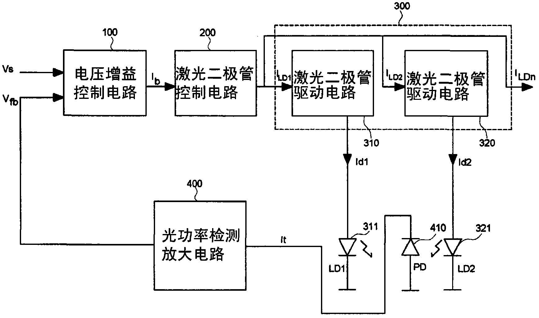
[0018] First, please refer to figure 2 , is a functional block diagram of the laser diode control device that can share the automatic power control circuit of the present invention. Such as figure 2 As shown, the laser diode control device includes a voltage gain control circuit 100, which can output a voltage and convert it into a current I b output to a laser diode control circuit 200, and then the output terminal of the laser diode control circuit 200 and a plurality of different laser diode drive circuits (for example: laser diode drive circuit 310 and laser diode drive circuit 320 are used to drive different laser diode drive circuits respectively. The driving circuit 300 composed of laser diodes 311 / 321) is connected, and then through the selection signal in the laser diode control circuit 200 (not shown in figure 2 in; will be image 3 shown and described in ) to select a laser diode drive circuit in the drive circuit 300 (for example: select the laser diode drive...


PUM


Abstract

The invention provides a laser diode control device capable of sharing an automatic power control circuit. The laser diode control device comprises a voltage gain control circuit, a laser diode control circuit, and a light power detecting amplification circuit. The laser diode control device is characterized in that the laser diode control circuit comprises a voltage detecting circuit and a soft starting circuit, wherein one input end of the voltage detecting circuit is connected with detection bias voltage, and another input end of the voltage detecting circuit is connected with reference voltage and supplies output voltage; the soft starting circuit is formed by a plurality of transistor current mirror circuits; the load ends of the transistor current mirror circuits are connected with a plurality of laser diode driving circuits, and the reference current ends of the current mirror circuits are connected with one end of a resistor; the other end of the resistor is connected with the emitter end of a transistor; and the base end of the crystal tube is connected with a capacitor and the output voltage.

Description

technical field [0001] The present invention relates to a laser diode control device, in particular to a laser diode control device with a shared automatic power control circuit, which consists of the laser diode control circuit, built-in soft start circuit and The design of the laser diode drive circuit can increase the stable current gain to drive the laser diode. Background technique [0002] With the advancement of computer technology and the popularization of the network, optical drives have become a necessity in daily life. For example, users can access a large amount of information by connecting a personal computer to the network, and then download and save the data to be used. Save to a disc. In addition, when data is to be stored in an optical disc or when data is to be read from an optical disc, it must be executed by an optical drive (CD-RW). [0003] The optical drive uses the optical principle to access data, that is, the reading and writing actions must be pe...

Claims


Application Information

Patent Timeline
IPC IPC(8): G11B7/004G11B7/125
Inventor 李灯辉李仕成
Owner AMTEK SEMICON
Why Eureka
Try Eureka