
An interconnection structure of a solar wing cell assembly and its preparation process

A technology of solar wings and solar cells, which is applied to solar panel accessories, wings, electrical components, etc., can solve the problems of unfavorable laying area utilization, complex structure, improvement and other problems, so as to improve the utilization rate of the laying area of ​​components, and improve the efficiency of the laying area. The effect of shortening the distance between cloth and reducing the weight of the structure

Active Publication Date: 2021-06-11
48TH RES INST OF CHINA ELECTRONICS TECH GROUP CORP
View PDF5 Cites 0 Cited by
  • Summary
  • Abstract
  • Description
  • Claims
  • Application Information

AI Technical Summary

Problems solved by technology

At the same time, for the laying and installation of flexible components on the wing frame, the edge of the component needs to be installed on the solid structure of the wing frame such as the wing rib and the front and rear edges. Usually, it needs to be installed on both sides of the rib and the rib edge, resulting in a large gap between the components along the direction of the wing span, which is not conducive to the further improvement of the utilization rate of the laying area
At the same time, interconnection structures such as junction boxes, cables, and docking plugs are heavy, and the cables need to go around through the rib structure to connect with adjacent components. At the same time, a fixed structure needs to be added to prevent it from shaking. The structure is complex and increases. Useless weight is reduced, which is not conducive to the further reduction and simplification of solar wing weight

Method used


Image

  • An interconnection structure of a solar wing cell assembly and its preparation process
  • An interconnection structure of a solar wing cell assembly and its preparation process
  • An interconnection structure of a solar wing cell assembly and its preparation process

Examples


Embodiment 1

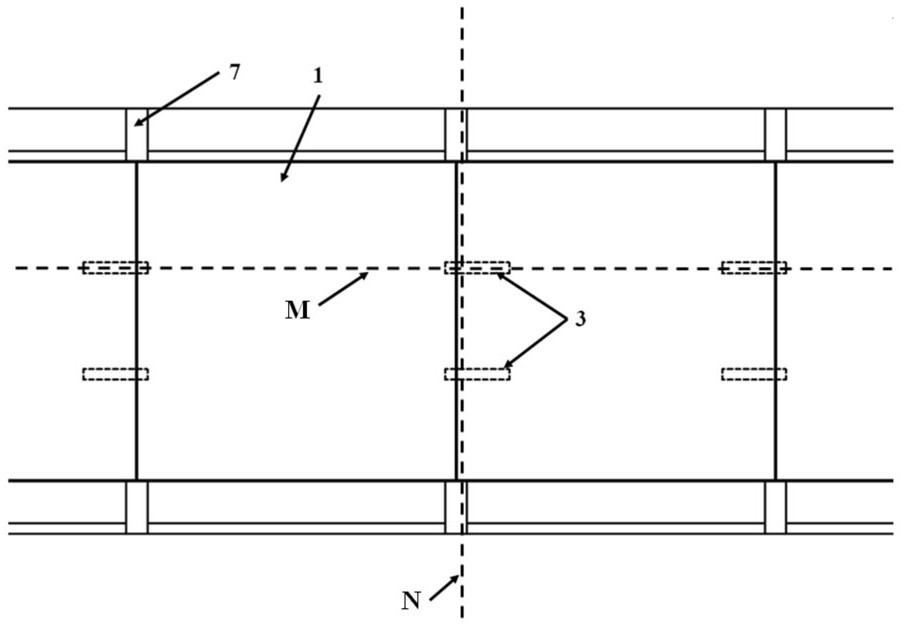
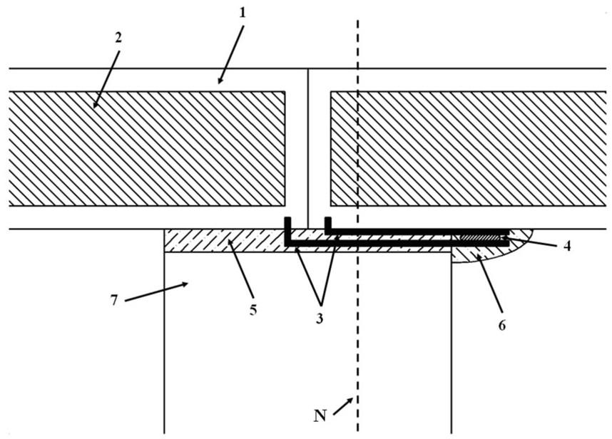
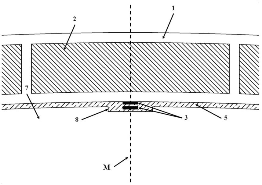
[0058] An interconnection structure of solar wing battery components of the present invention, comprising: two pairs of positive and negative lead-out wires provided by a single battery component, the positive and negative lead-out lines are flat conductor lead-out lines, and the lead-out points of the positive and negative lead-out wires are Located at both ends of the battery assembly along the span of the wing.

[0059] The lead-out points of the lead-out wire pairs interconnected by adjacent battery components are set close to the joint surface of adjacent battery components, and are relatively arranged on both sides of the joint face of adjacent battery components. Lead out along the same side direction, close to the back of the battery module in an overlapping position relationship, and finally connect.

[0060] Adjacent battery assemblies are connected to wing ribs.

[0061] For details of the interconnection structure in this embodiment, please refer to Figure 1 ~ F...

Embodiment 2

[0076] An interconnection structure of solar wing battery components of the present invention, comprising: two pairs of positive and negative lead-out wires provided by a single battery component, the positive and negative lead-out lines are flat conductor lead-out lines, and the lead-out points of the positive and negative lead-out wires are Located at both ends of the battery assembly along the span of the wing.

[0077] The lead-out points of the lead-out wire pairs interconnected by adjacent battery components are set close to the joint surface of adjacent battery components, and are relatively arranged on both sides of the joint face of adjacent battery components. Lead out along the same side direction, close to the back of the battery module in an overlapping position relationship, and finally connect.

[0078] Adjacent battery assemblies are connected to wing ribs.

[0079] For details of the interconnection structure in this embodiment, please refer to Figure 1 ~ F...

Embodiment 3

[0095] An interconnection structure of solar wing battery components of the present invention, comprising: two pairs of positive and negative lead-out wires provided by a single battery component, the positive and negative lead-out lines are flat conductor lead-out lines, and the lead-out points of the positive and negative lead-out wires are Located at both ends of the battery assembly along the span of the wing.

[0096] The lead-out points of the lead-out wire pairs interconnected by adjacent battery components are set close to the joint surface of adjacent battery components, and are relatively arranged on both sides of the joint face of adjacent battery components. Lead out along the same side direction, close to the back of the battery module in an overlapping position relationship, and finally connect.

[0097] Adjacent battery assemblies are connected to wing ribs.

[0098] For details of the interconnection structure in this embodiment, please refer to Figure 1 ~ F...


PUM


Abstract

The invention discloses an interconnection structure of a solar wing cell assembly and a preparation process thereof. The interconnection structure includes more than one pair of positive and negative lead-out wires provided in a single battery assembly, and adopts flat conductor lead-out wires. The lead-out points of the lead-out wire pairs interconnected by adjacent battery assemblies are arranged close to the assembly interface and are arranged opposite to each other. On both sides of the junction surface, the interconnected lead-out pairs are drawn out from the back of the battery module along the same side direction, and are routed closely to the back of the battery module in an overlapping position and finally connected, and the adjacent battery modules are connected to the wing rib Location. The preparation process includes the preparation of the lead wire and the lead wire structure, the battery assembly installation, the lead wire interconnection pair overlap connection and the lead wire insulation protection. Compared with the traditional interconnection structure, the interconnection structure greatly simplifies the interconnection structure, reduces the weight of the interconnection structure, reduces the battery cell spacing area between components, and improves the utilization rate of the laying area of ​​the solar cells.

Description

technical field [0001] The invention belongs to the technical field of solar cell preparation, and in particular relates to an interconnection structure of a solar wing cell assembly and a preparation process thereof. Background technique [0002] As a clean and renewable energy source, solar cells have been greatly commercialized worldwide. [0003] Among them, conventional crystalline silicon solar cells have certain advantages in terms of process maturity, cost, efficiency, reliability, etc., and occupy a considerable market share in the solar cell market. Conventional crystalline silicon solar cell modules are generally rigid components, which are products obtained by laminating or encapsulating tempered glass, conventional crystalline silicon cells, adhesives, and transparent films. They are more suitable for large buildings such as solar power stations and roofs. use. [0004] Compared with conventional rigid solar cells, flexible solar cells have the characteristics...

Claims


Application Information

Patent Timeline
Patent Type & Authority Patents(China)
IPC IPC(8): H01L31/05H01L31/18B64C3/00
CPCB64C3/00B64D2211/00H01L31/0508H01L31/188Y02E10/50Y02P70/50
Inventor 黄齐鸣张建国杨晓生周洪彪陆运章
Owner 48TH RES INST OF CHINA ELECTRONICS TECH GROUP CORP
Learn More