Bridge type DC energy consumption device and control method

An energy-consuming device and control method technology, applied in circuit devices, emergency protection circuit devices, emergency protection circuit devices for limiting overcurrent/overvoltage, etc. Can not send and other problems, to enhance the ability to suppress the overvoltage of the DC line, reduce the risk of overvoltage, and save the effect of charging resistors

Pending Publication Date: 2019-03-29
NR ELECTRIC CO LTD +1
View PDF1 Cites 7 Cited by
  • Summary
  • Abstract
  • Description
  • Claims
  • Application Information

AI Technical Summary

Problems solved by technology

DC energy consumption devices are mainly used in the application scenarios of new energy power generation and transmission. If the power generation end is an inertial power source similar to wind power, when the power receiving end fails, because the power cannot be sent out, the energy will be accumulated on the DC side, resulting in the failure of the DC transmission line. The voltage rise will cause harm to the safe operation of the equipment
[0003] The commonly used technical solution in the prior art is to use power semiconductor devices, such as IGBT directly connected in series and a centralized resistance solution. The IGBT valve string is subjected to high voltage, and the concentrated resistance consumes energy. The consistency of opening and closing is extremely high. Once there is inconsistency, some valve sections will be overpressured and burned. Due to the continuous opening and closing during work, the risk of device damage is high.
[0004] There is a technical solution to propose a modular solution, but the solution has the defects of large number of components, high cost, and low reliability, such as the solution proposed in the patent CN102132484B converter with distributed braking resistors, such as figure 2 As shown, the main defect of this scheme is that the potential of the bridge arm formed by the diode is complex: the upper tube of the diode bridge arm is connected to the adjacent module, and the capacitor cannot clamp it, and when the device is running, due to the operating mode Complicated, when the work between modules is not synchronized, the potential between the modules is uncertain, and the diode has the risk of overvoltage breakdown; at the same time, the number of devices in this scheme is large, including 4 groups of power semiconductor devices. The failure rate and cost are high; moreover, the module of this scheme contains two bridge arms composed of power semiconductor devices, and there is a potential connection between the bridge arms, which increases the difficulty of structural design

Method used


Image

  • Bridge type DC energy consumption device and control method
  • Bridge type DC energy consumption device and control method
  • Bridge type DC energy consumption device and control method

Examples


Embodiment Construction

[0060] The present invention will be further described below in conjunction with accompanying drawing.

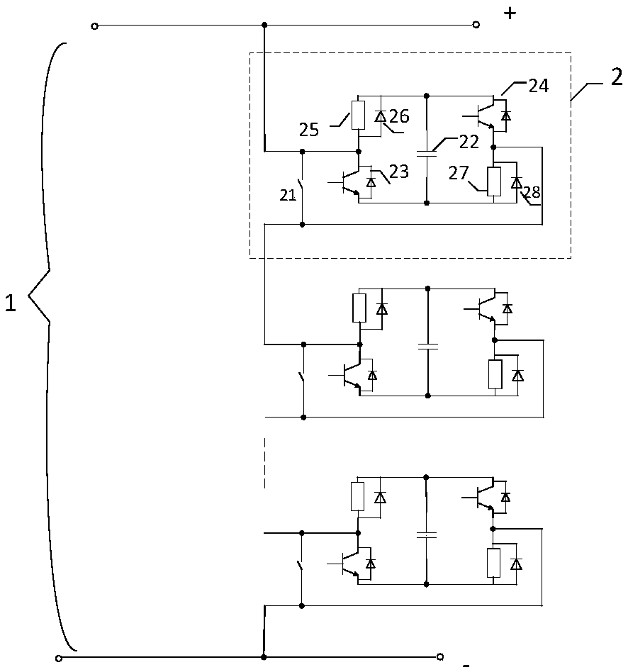
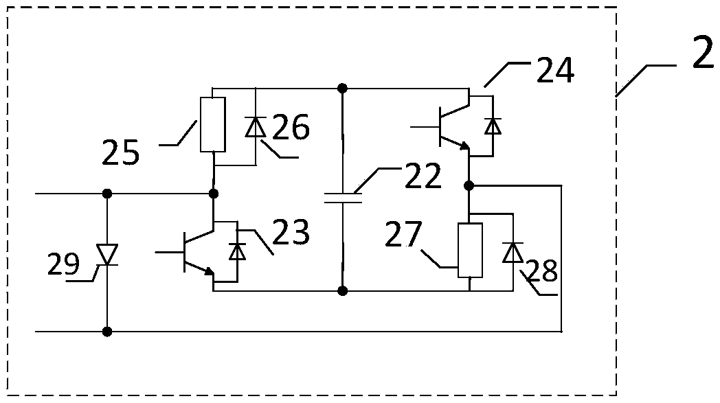
[0061] Such as figure 1 As shown, a bridge-type DC energy-consuming device 1 of the present invention includes at least two bridge-type energy-consuming modules 2, and the bridge-type energy-consuming modules are connected in parallel by a DC capacitor, a first energy-consuming branch, and a second energy-consuming branch Connection structure; the first energy consumption branch is composed of the first power semiconductor device and the first energy consumption resistor connected in series, the connection point of the two is drawn as the first lead end, the other end of the first energy consumption resistor is connected to the positive pole of the DC capacitor connected; the second energy-consuming branch is composed of a second power semiconductor device connected in series with a second energy-dissipating resistor, the connection point of the two is taken out as the sec...


PUM


Abstract

The invention discloses a bridge type DC energy consumption device which comprises at least two bridge type energy consumption modules. Each bridge type energy consumption module is formed by connecting a DC capacitor, a first energy consumption branch and a second energy consumption branch in parallel. The first energy consumption branch is formed by connecting a first power semiconductor deviceand a first energy consumption resistor in series, and a connection point of the two is led out as a first lead-out end. The second energy consumption branch is formed by serially connecting a secondpower semiconductor device and a second energy consumption resistor, and a connecting point of the two is led out as a second lead-out end. The at least two bridge type energy consumption modules areconnected in series in the same direction to form the bridge type DC energy consumption device. The invention further discloses a control method based on the bridge type DC energy consumption device.When the voltage of a DC line rises, the power semiconductor device is controlled to control the on-off of the energy consumption resistor so as to stabilize the direct-current voltage. When the DC line is short-circuited, the first energy consumption resistor and the second energy consumption resistor are connected in series to limit the direct current capacitance current. The device is high in cost performance, high in reliability and easy to implement.

Description

technical field [0001] The invention belongs to the technical field of high-power electric current conversion, and in particular relates to a bridge-type DC energy consumption device and a control method. Background technique [0002] In HVDC power transmission system, DC energy consumption device is a crucial equipment. DC energy consumption devices are mainly used in the application scenarios of new energy power generation and transmission. If the power generation end is an inertial power source similar to wind power, when the power receiving end fails, because the power cannot be sent out, the energy will be accumulated on the DC side, resulting in the failure of the DC transmission line. The voltage rise will cause harm to the safe operation of the equipment. [0003] The commonly used technical solution in the prior art is to use power semiconductor devices, such as IGBT directly connected in series and a centralized resistance solution. The IGBT valve string is subjec...

Claims


Application Information

Patent Timeline
Patent Type & Authority Applications(China)
IPC IPC(8): H02J3/36H02H9/02
CPCH02H9/02H02J3/001H02J3/36Y02E60/60
Inventor 谢晔源李海英姜田贵曹冬明李九虎
Owner NR ELECTRIC CO LTD
Why Eureka
Try Eureka