
Loudspeaker structure

A speaker and inner frame technology, applied in the speaker field, can solve the problems of small design specifications, unstable sound output, and limited speaker space.

Inactive Publication Date: 2019-03-29
TIINLAB AUDIO TECH
View PDF5 Cites 0 Cited by
  • Summary
  • Abstract
  • Description
  • Claims
  • Application Information

AI Technical Summary

Problems solved by technology

[0002] The existing loudspeaker structure is an electronic device that converts electronic signals into sound signals, mainly because there will be mutual repulsion between the voice coil and the magnet after it is energized, forming a similar piston-like effect, thus pushing the diaphragm in front of the magnet along the trend, The sound wave in front of the diaphragm is radiated to the surroundings. In addition, the ring-shaped elastic wave is used to fix the voice coil in the structure. Since the elastic wave is arranged between the magnet and the diaphragm, the volume of the speaker cannot be reduced, nor can it Due to the limitation of volume, it cannot be applied to many electronic products that emphasize lightness, lightness and shortness.
[0003] The current high-tech electronic products (such as thin TVs, notebook computers, tablet computers, PDAs, MP3 players or mobile phones, etc.), in order to meet the characteristics of the overall model with thin and light or easy to carry, the overall design specifications , the size of the production is very small, and the space for accommodating the speaker is also very limited, so many flat-panel speakers are born accordingly, and this type of smaller-sized flat-panel speaker is often in pursuit of thinness, so the speaker will be The internal elastic wave structure is removed to make the overall structure thinner, but when the structure is changed in this way, at low power output, since the vibration amplitude of the diaphragm is not large, distortion is not easy to occur; but at high power output, The vibration amplitude of the diaphragm is relatively large, and at this time, the diaphragm will produce unbalanced vibration and shaking, which also makes the output of the sound very unstable. Therefore, the existing thin speakers can only meet the low power output performance, which is not suitable for applications. For high power output, there will be corresponding restrictions

Method used


Image

  • Loudspeaker structure
  • Loudspeaker structure
  • Loudspeaker structure

Examples


Embodiment Construction

[0065] Other technical contents, features and effects of the present invention will be clearly presented in the following detailed description of preferred embodiments with reference to the accompanying drawings.

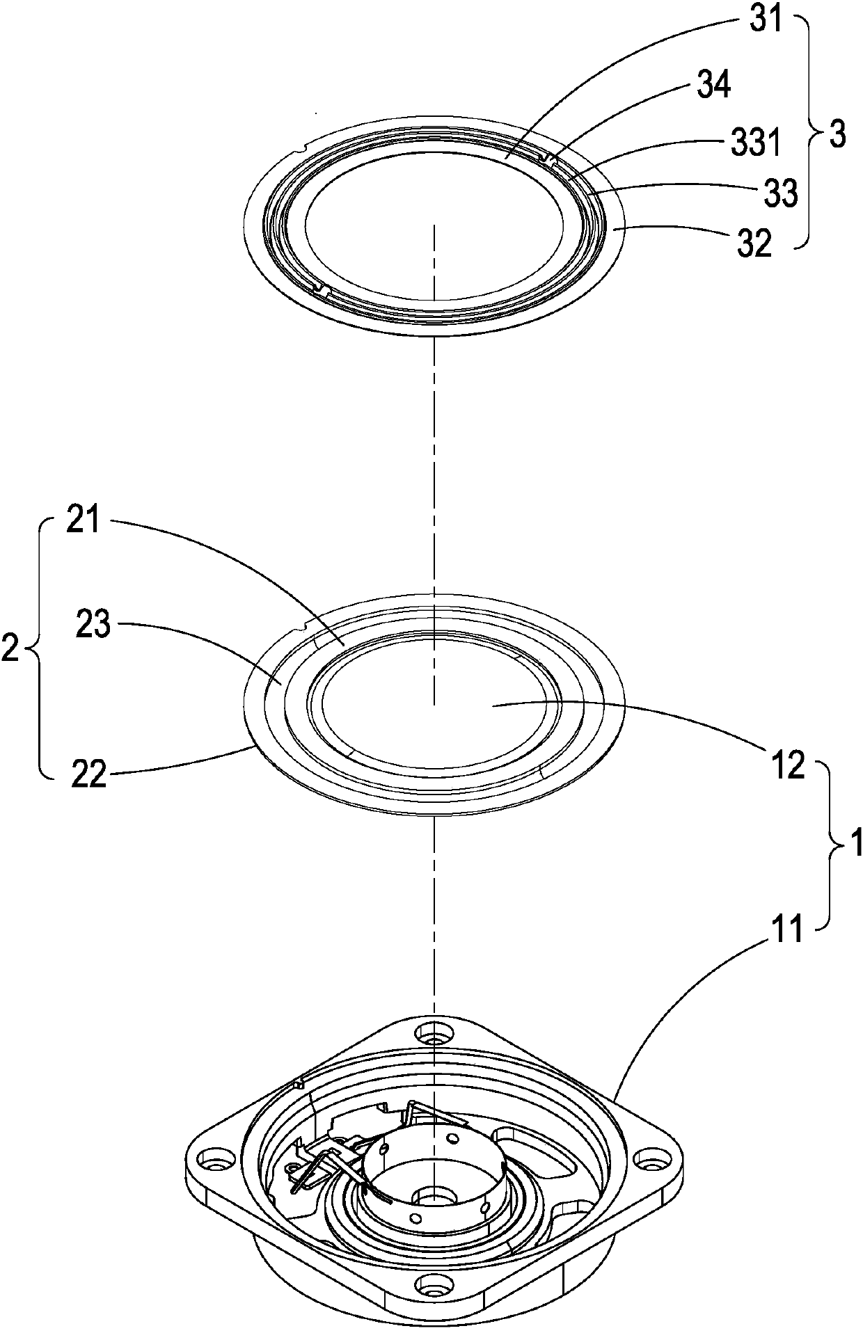
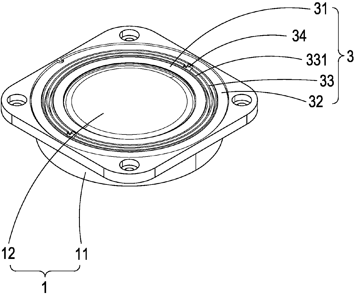
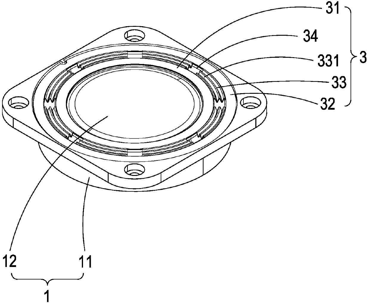
[0066] see Figure 1A~Figure 1C , is a schematic diagram of the three-dimensional structure decomposition of the first embodiment of the loudspeaker structure of the present invention, a schematic diagram of the combination of the three-dimensional structure, and a schematic diagram of another state of the wave element. As shown in the figure, the loudspeaker structure includes a loudspeaker unit 1, a hanging edge 2 and an elastic wave member 3, wherein, the loudspeaker unit 1 has at least a frame 11 and a diaphragm 12, and the loudspeaker unit 1 also has the components of the general loudspeaker such as a voice coil and a dust cover. It is prior art, so it is not additionally disclosed in the accompanying drawings;

[0067]And this hanging edge 2 is made up of an ...


PUM


Abstract

The invention discloses a loudspeaker structure, the loudspeaker structure comprises a loudspeaker monomer, a dangling edge and an elastic wave piece, wherein the loudspeaker monomer at least comprises a cone frame and a vibrating diaphragm, the elastic wave piece is composed of an inner framework body, an external framework body and at least one wave piece, the dangling edge and the elastic wavepiece can be attached together and arranged upside down, moreover, the vibrating diaphragm is combined under or over the dangling edge and the elastic wave piece; when the loudspeaker monomer is driven to make sounds, the vibrating diaphragm vibrates synchronously, right now, the elastic wave piece can be used for locating the vibrating diaphragm and balancing a vibrating state of the vibrating diaphragm, thus, when the loudspeaker is driven by high power, the monomer can be effectively thinned and the vibrating diaphragm is prevented from generating unbalanced vibration and causing occurrenceof a condition where output audio is unstable.

Description

technical field [0001] The present invention relates to a loudspeaker, especially a loudspeaker that can be fixed on the sound-out surface of a single speaker with elastic wave parts, and the single body can be thinned by elastic wave parts, and at the same time, the diaphragm can be stabilized so that it can balance the vibration structure. Background technique [0002] The existing loudspeaker structure is an electronic device that converts electronic signals into sound signals, mainly because there will be mutual repulsion between the voice coil and the magnet after it is energized, forming a similar piston-like effect, thus pushing the diaphragm in front of the magnet along the trend, The sound wave in front of the diaphragm is radiated to the surroundings. In addition, the ring-shaped elastic wave is used to fix the voice coil in the structure. Since the elastic wave is arranged between the magnet and the diaphragm, the volume of the speaker cannot be reduced, nor can i...

Claims


Application Information

Patent Timeline
Patent Type & Authority Applications(China)
IPC IPC(8): H04R9/06H04R9/02
CPCH04R9/02H04R9/06H04R2400/11
Inventor 陈政元蔡良潭
Owner TIINLAB AUDIO TECH
Learn More