
Dimming interface control circuit and method, and LED driving system, chip and method

A dimming interface and control circuit technology, applied in the field of power electronics, can solve the problems of low dimming accuracy, small application range, and high cost, and achieve the effects of high dimming accuracy, wide application range, and low cost

Pending Publication Date: 2019-03-29
SHANGHAI BRIGHT POWER SEMICONDUCTOR CO LTD
View PDF0 Cites 6 Cited by
  • Summary
  • Abstract
  • Description
  • Claims
  • Application Information

AI Technical Summary

Problems solved by technology

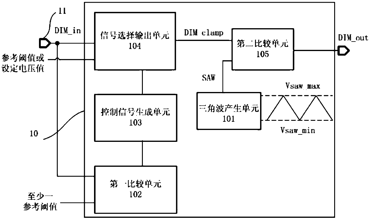
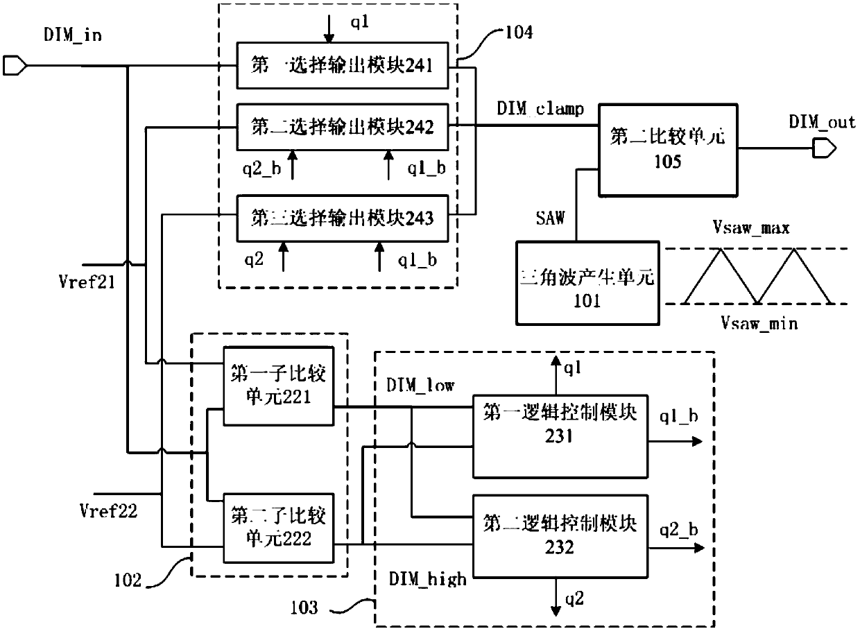
[0003] The existing dimming technology is divided into: 1) individual PWM dimming; 2) individual Analog dimming; 3) both PWM dimming and Analog dimming, but divided into different interfaces; 4) PWM dimming and Analog dimming is available, and share the same interface, but the two dimming signals are processed and divided into two unrelated control signals, which can only be controlled separately. The Analog signal is processed into a DC signal to modulate the constant current reference signal Vref_CC, or Compensate the sampling feedback value of the output current, and the PWM signal directly controls the power transistor (Power MOS)
[0004] Corresponding technical problems: the above-mentioned dimming techniques 1) and 2) are both aimed at a single dimming method, and cannot be compatible with the two, and the scope of application is small; the above-mentioned dimming technique 3) needs an additional interface, and when PWM dimming, it needs to be in Add an external filter capacitor to the analog dimming interface, filter it into a DC signal and then modulate the constant current reference signal Vref_CC, or compensate the sampling feedback value of the output current, which is equivalent to Analog dimming, so the cost is high and the dimming accuracy is high. The above-mentioned dimming technology 4) although only one interface is needed, the two dimming signals are controlled separately, and the PWM dimming method cannot achieve an average constant of a single-stage high power factor (Power Factor, hereinafter referred to as PF). streaming application

Method used


Image

  • Dimming interface control circuit and method, and LED driving system, chip and method
  • Dimming interface control circuit and method, and LED driving system, chip and method
  • Dimming interface control circuit and method, and LED driving system, chip and method

Examples


Embodiment Construction

[0026] The following will clearly and completely describe the technical solutions in the embodiments of the present invention with reference to the drawings in the embodiments of the present invention. Apparently, the described embodiments are only some of the embodiments of the present invention, but not all of them. Based on the embodiments of the present invention, all other embodiments obtained by those skilled in the art without creative efforts fall within the protection scope of the present invention.

[0027] The terms "first", "second", "third", etc. (if any) in the description and claims of the present invention and the drawings are used to distinguish similar objects and not necessarily to describe a specific order or priority. It should be understood that the items so described are interchangeable under appropriate circumstances. Furthermore, the terms "comprising" and "having", as well as any variations thereof, are intended to cover a non-exclusive inclusion. ...


PUM


Abstract

The invention discloses a dimming interface control circuit and method, and an LED driving system, chip and method, being characterized by: being able to be compatible with PWM dimming and analog dimming only by using one interface while two ports are not required and extra external filter capacitors are not required, thus being low in cost. The dimming interface control circuit and method, and the LED driving system, chip and method can process the received PWM signal or analog signal into a PWM signal, can perform chopping on the constant current reference voltage in a pulse width mode, is high in the dimming accuracy, is high in the dimming depth, and is preferable in the batch consistency.

Description

technical field [0001] The invention relates to the technical field of power electronics, in particular to a dimming interface control circuit and method suitable for an AC / DC switching power supply and its control system, an LED driving system, a chip and the method. Background technique [0002] "Dimmable light" is an important advantage of LED light sources over traditional light sources. Precisely controlling the luminous intensity of LED light sources can create different atmospheres and meet people's diverse needs for lighting. There are two most common ways to realize LED dimming: analog dimming (Analog Dimming) and pulse width modulation dimming (PWM Dimming). Analog dimming adjusts the brightness of the light source by changing the current amplitude of the LED light source. The larger the current, the brighter the LED light source, and the smaller the current, the darker the LED light source. PWM dimming is to use the pulse width modulation signal to repeatedly tur...

Claims


Application Information

Patent Timeline
IPC IPC(8): H05B33/08H05B44/00
CPCH05B45/00H05B45/10
Inventor 蔡晓辉张富强郜小茹
Owner SHANGHAI BRIGHT POWER SEMICONDUCTOR CO LTD
Learn More