Steel pipe mechanical-oiling equipment

An oiling and mechanical technology, applied in the direction of coating, liquid coating device on the surface, etc., can solve the problems of low coating efficiency, uneven coating, uneven coating, etc., to improve the quality of oil coating and facilitate coating Oil, the effect of ensuring the quality of oil coating

Inactive Publication Date: 2019-04-02
HUNAN UNIV OF SCI & ENG
View PDF0 Cites 25 Cited by
  • Summary
  • Abstract
  • Description
  • Claims
  • Application Information

AI Technical Summary

Problems solved by technology

It can overcome the problems of uneven coating and low coating efficiency caused by the instability of coating equipment during manual coating; at the same time, it can overcome the problem of waste of raw materials caused by repeated coating by mechanical coating; The problem of uneven coating caused by the inability to adjust the coating angle and spraying amount in time according to the actual effect

Method used


Image

  • Steel pipe mechanical-oiling equipment
  • Steel pipe mechanical-oiling equipment
  • Steel pipe mechanical-oiling equipment

Examples


Embodiment 1

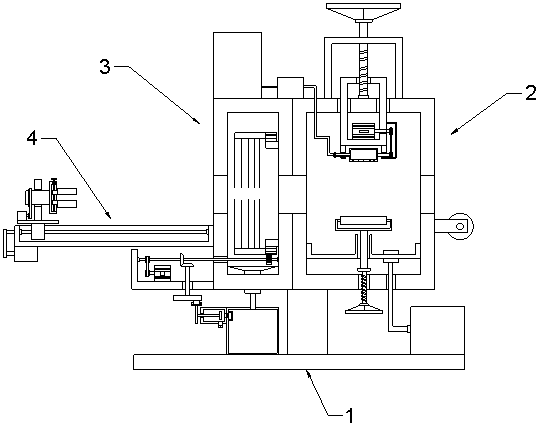
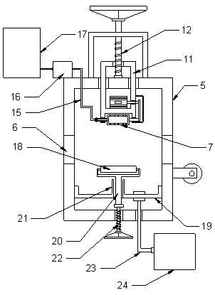
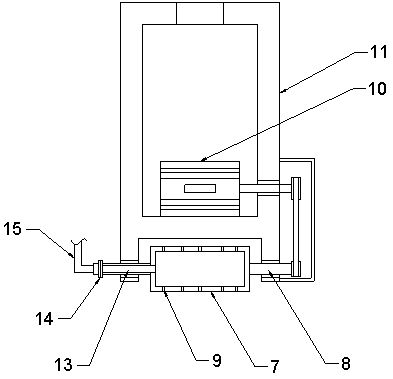
[0027] see Figure 1-7, in an embodiment of the present invention, a mechanical oiling equipment for steel pipes includes a base 1, an oiling mechanism 2 and a dust removal mechanism 3; the oiling mechanism 2 includes an oiling tank 5 fixedly connected to the base 1, and the oiling tank serves as a In the working space of oil coating, the two ends of the oil coating tank 5 are provided with circular through holes for steel pipes to enter. , the oiling tank 5 is provided with an oiling roller 7, the oiling roller 7 is a round hair roller, so that the oiling roller 7 can fully contact with the circumferential surface of the steel pipe, so that the anti-rust oil can be evenly applied to the circumference of the steel pipe On the surface, the oiling roller 7 is rotatably connected with a lifting frame 11, and the lower end surface of the lifting frame 11 is in the shape of an arc plate, so as to prevent the oiling roller 7 from being in close contact with the steel pipe surface wh...

Embodiment 2

[0031] see Figure 8 and Figure 9 The difference between this embodiment and Embodiment 1 is that: the left side of the dust removal box 25 is provided with a feed mechanism 4, the feed mechanism 4 includes a sliding frame 43 and drives the sliding frame 43 to move the linear screw module 44 laterally, and the linear wire The rod module 44 includes a screw rod, a screw motor and a linear guide rail, the screw rod motor drives the screw rod to rotate, and the screw rod drives the sliding frame 43 to move laterally on the linear guide rail, which is a prior art, and the present application will not repeat it; the sliding frame 43 is nested with a cylindrical drum 45, the drum 45 is rotationally connected with the sliding frame 43 through a bearing sleeve, the right side of the drum 45 is fixedly connected with a clamping frame 47, and the clamping frame 47 is nested with a third screw rod 49 , the third threaded mandrel 49 runs through and is threadedly connected with clamping...


PUM


Abstract

The invention discloses steel pipe mechanical-oiling equipment which comprises a base, an oiling mechanism, a dust removing mechanism and a feeding mechanism, wherein the oiling mechanism comprises anoiling tank which is fixedly connected with the base; an oiling roll is arranged in the oiling tank; uniformly-distributed overflow holes are formed in the circumferential surface of the oiling roll;the dust removing mechanism comprises a dust removing tank; and a ring-shaped brush is arranged in the dust removing tank. The steel pipe mechanical-oiling equipment disclosed by the invention has the beneficial effects that through the arrangement of the hollow oiling roll provided with the overflow holes as well as a spreading roll capable of rising and falling, the surface of a steel pipe canbe uniformly coated with anti-rust oil, thereby improving the oiling quality when the consumption of the anti-rust oil is reduced; and through the arrangement of the ring-shaped brush, a dust collecting hood and a dust collecting tank which communicates with a suction piston cylinder, the efficient dust removing operation on the to-be-oiled steel pipe can be achieved, thereby guaranteeing the oiling quality; and through the arrangement of a rotating cylinder and a sliding frame which are equipped with a clamping mechanism, the steel pipe can be rotated when fed, thereby facilitating the oilingoperation on the circumferential surface of the steel pipe.

Description

technical field [0001] The invention relates to the field of electromechanical equipment, in particular to mechanical oiling equipment for steel pipes. Background technique [0002] Electromechanical equipment, that is, the combination of applied mechanical technology and electronic technology. With the rapid development and wide application of computer technology, mechatronics technology has achieved unprecedented development and has become a comprehensive computer and information technology, automatic control technology, sensor detection Technology, servo transmission technology and mechanical technology are intersecting system technologies, which are developing in the direction of opto-mechanical integration technology, and the scope of application is becoming wider and wider. In the field of industrial machinery, electromechanical equipment has realized the automatic processing of mechanical parts, which greatly Improve the processing efficiency of mechanical parts. [...

Claims


Application Information

Patent Timeline
Patent Type & Authority Applications(China)
IPC IPC(8): B05C1/10B05C1/06B05C9/10B05C13/02B05C11/02
CPCB05C1/06B05C1/10B05C9/10B05C11/025B05C13/02
Inventor 刘志壮张文昭包本刚朱湘萍王飞廖子涵
Owner HUNAN UNIV OF SCI & ENG
Why Eureka
Try Eureka