Automatic grain thrower for farm

A kind of lift machine, automatic technology, applied in the field of lift machine, can solve the problems of large dust, smoke and dust around, poor separation effect, etc., and achieve the effect of easy contact with air flow

Active Publication Date: 2019-04-02
张家界数字乡村有限公司
View PDF11 Cites 1 Cited by
  • Summary
  • Abstract
  • Description
  • Claims
  • Application Information

AI Technical Summary

Problems solved by technology

[0003] The structure and purpose of the existing lifting machine are relatively simple, and it only has the ability to separate the sundries and the separation effect is not good; the grain is only separated once by the blower, and the separated grain cannot be collected in time, and it needs to be bagged manually; the existing The smoke and dust of the current hoisting machine is too large when it is working, and the separated sundries are not collected and packed, resulting in a lot of dust around it; in summary, the existing hoisting machine cannot fully separate the impurities in the grain, and at the same time, the grain cannot be packed Bag packing and separated sundries cannot be automatically squeezed and collected

Method used


Image

  • Automatic grain thrower for farm
  • Automatic grain thrower for farm
  • Automatic grain thrower for farm

Examples


Embodiment Construction

[0028] The technical solutions in the embodiments of the present invention will be clearly and completely described below in conjunction with the accompanying drawings in the embodiments of the present invention; obviously, the described embodiments are only some embodiments of the present invention; rather than all embodiments. Based on the embodiments of the present invention; all other embodiments obtained by persons of ordinary skill in the art without creative work; all belong to the protection scope of the present invention.

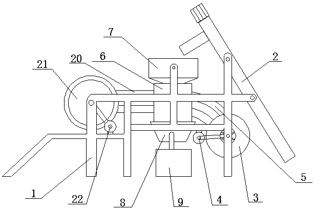
[0029] see Figure 1-9 , an automatic lifting machine for farms, comprising a frame 1, the right end of the frame 1 is movably connected with a screw conveying device 2, and the lower right side of the frame 1 is rotatably connected with a blowing device 3; the left side of the blowing device 3 is provided with a second A motor 4, the first motor 4 is fixedly connected to the frame 1; the left side of the blast device 3 is fixedly connected to the ...


PUM


Abstract

The invention discloses an automatic grain thrower for a farm. The automatic grain thrower for the farm comprises a machine frame, the right end of the machine frame is movably connected with a spiralconveying device, and a blower device is rotatably connected to the lower right side of the machine frame; a first motor is arranged on the left side of the blower device, and the left side of the blower device is fixedly connected with a first blast pipe; a screening device is fixedly connected to the left end of the first blast pipe, a funnel is arranged at the top of the screening device, a distributing device is arranged under the screening device, and packing devices are arranged on the front side and the rear side of the distributing device; the screening device comprises a screening device body, and the left side and the right side of the inner part of the screening device body are correspondingly and fixedly connected with flow limiting plates and filtering sieves; rectangle openings are formed in the positions under the filtering sieves, rollers are arranged on the upper parts of the positions between the flow limiting plates and the filtering sieves, and the front ends and the rear ends of the rollers are rotatably connected with the inner part of the screening device body. When the automatic grain thrower is used, impurities can be separated from grains fully, and meanwhile the separated grains can be packed and the separated impurities can be subjected to automatic extrusion and collection.

Description

technical field [0001] The invention relates to the field of field lifters, and more specifically relates to an automatic field lifter for farms. Background technique [0002] The lifting machine is a kind of equipment for simple cleaning of grain, which can remove light impurities and large impurities in grain, so as to facilitate grain storage; its working principle is to separate the lighter impurities with airflow, and the larger and heavier impurities The impurities are filtered through the sieve to realize the separation of impurities inside the grain. [0003] The structure and purpose of the existing lifting machine are relatively simple, and it only has the ability to separate the sundries and the separation effect is not good; the grain is only separated once by the blower, and the separated grain cannot be collected in time, and it needs to be bagged manually; the existing The smoke and dust of the current hoisting machine is too large when it is working, and the...

Claims


Application Information

Patent Timeline
Patent Type & Authority Applications(China)
IPC IPC(8): B07B9/00B07B1/00B07B4/02B07B7/00B07B11/06
CPCB07B1/00B07B4/02B07B7/00B07B9/00B07B11/06
Inventor 聂林章
Owner 张家界数字乡村有限公司
Why Eureka
Try Eureka