Method for realizing ultra-high precision circular inductosyn

A technology of circular induction synchronizer and induction synchronizer, which is applied in the field of realizing ultra-high precision circular induction synchronizer, and can solve the problems affecting the engraved line processing of the synchronizer, the large size of the multi-tooth indexing table, and the limitation of the pole number of the engraved line, etc. Achieve the effects of variable and flexible number of marking poles, improved precision level, and convenient operation

Inactive Publication Date: 2019-04-02
JIUJIANG JINGDA MEASUREMENT TECH
View PDF0 Cites 1 Cited by
  • Summary
  • Abstract
  • Description
  • Claims
  • Application Information

AI Technical Summary

Problems solved by technology

A synchronizer with more poles requires a multi-tooth indexing table with higher angular resolution. For a multi-tooth indexing table, high angular resolution makes the number of teeth too large, resulting in an oversized multi-tooth indexing table. Difficult to implement, unreliable performance
Excessive size of the multi-tooth indexing table will also affect the engraved line processing of the synchronizer
Affected by the multi-tooth indexing table used, the number of marking poles is limited (not more than 720 poles); the other is corrosion marking, which has a fast processing speed, but the marking accuracy is affected by the marking template, and the overall The accuracy of the marking line is not high, and due to cost and equipment problems, the number of poles of the marking template is not many, resulting in a limit on the number of marking poles (not more than 720 poles)

Method used


Image

  • Method for realizing ultra-high precision circular inductosyn
  • Method for realizing ultra-high precision circular inductosyn

Examples


Embodiment Construction

[0030] The present invention will be described in further detail below in conjunction with the embodiments and with reference to the accompanying drawings.

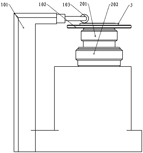
[0031] like figure 2 As shown, the multi-tooth indexing table 202 of X teeth and the multi-tooth indexing table 201 of Y teeth constitute a differential indexing system, and the coaxiality of the two multi-tooth indexing tables is required to be better than 0.003mm. To adjust the differential indexing system, it is required that the accuracy of a single multi-tooth indexing table is not greater than 0.2", and the comprehensive differential accuracy is not greater than 0.4", where: X>Y>300, and X is an integer multiple of 180, then the two The angular resolution of the difference is [360(X-Y) / XY]°.

[0032] like figure 2 As shown in the figure, the differential indexing system is installed on the synchronizer marking tooling 102 in the marking processing system, and joint adjustment is carried out to ensure that the pr...


PUM


Abstract

The invention discloses a method for realizing ultra-high precision circular inductosyn. The method for realizing the ultra-high precision circular inductosyn completes ultra-high precision small-angle indexing by a high-precision scribing device formed by a differential indexing system and a scribing processing system. The differential indexing system is composed of two multi-tooth indexing tables with different tooth numbers. The scribing processing system is composed of a high precision milling machine and a synchronizer scribing tool. According to the method for realizing the ultra-high precision circular inductosyn, small-angle rotation is provided through the differential indexing system, and the scribing processing system completes the circular concentricity of a synchronizer base plate and the winding processing to realize the processing of the high-precision circular inductosyn (the pole number is more than 720). The method for realizing the ultra-high precision circular inductosyn is convenient to operate, easy to realize and high in operability, is completed by relying on differential multi-tooth indexing technology and synchronizer high-precision scribing technology, solves the problem that the high-precision synchronizer winding cannot break through the limiting of 720 poles and the problem that the size is too large when the angle resolution of a single multi-tooth indexing table is high, and improves the precision grade of the circular inductosyn.

Description

technical field [0001] The invention relates to a circular induction synchronizer, in particular to a method for realizing an ultra-high precision circular induction synchronizer. Background technique [0002] The circular induction synchronizer is an electromagnetic induction position detection element. It is characterized by being insensitive to the influence of temperature, resistant to shock, vibration, high pressure, vacuum, and capable of continuous operation. At the same time, it has strong self-protection against pollutants, such as Oil, liquid, dust, dirt, salt spray. The circular induction synchronizer adopts high-precision scribing to realize multi-pole induction winding, which can achieve high precision (±1"). reliability. [0003] The highest precision that a circular induction synchronizer can achieve is ±1", and the bottleneck limiting the precision of the synchronizer is the limited number of poles of the winding. figure 1 As shown, the black part is the w...

Claims


Application Information

Patent Timeline
IPC IPC(8): B23C3/00B23Q16/02
CPCB23C3/00B23Q16/02
Inventor 任梦晴薄夫森周策周志仁张旭明
Owner JIUJIANG JINGDA MEASUREMENT TECH
Why Eureka
Try Eureka