A plastic integrated molding mold
A technology for molding molds and plastics, which is applied in the field of plastic integrated molding molds, can solve problems such as singleness, and achieve the effect of high operability and convenient production
- Summary
- Abstract
- Description
- Claims
- Application Information
AI Technical Summary
Problems solved by technology
Method used
Image

Examples
Embodiment 1
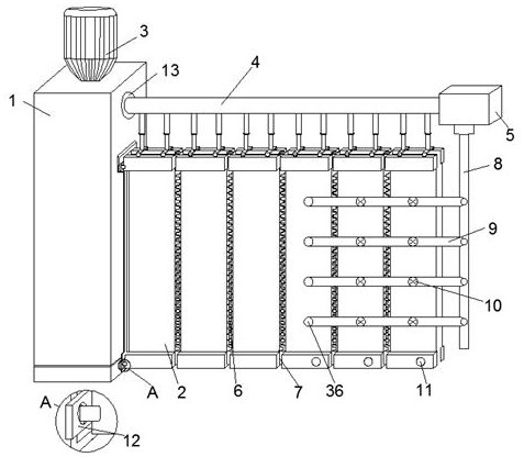
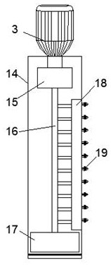
[0025] Embodiment 1: refer to Figure 1-2 , a plastic integrated molding mold, including a molding machine 1 and a feeder 3, and also includes a deformation mold 2 and an adjustment arm 4; and the pressurizing pump 17 are fixedly installed inside the cabinet 14, the feeder 3 is fixedly installed on the upper end of the cabinet 14, the feeder 3 is connected to the heating machine 15 pipes, and the bottom end of the heating machine 15 is fixedly connected with a plastic outlet pipe 16, The other end of the plastic outlet pipe 16 is fixedly connected with the booster pump 17, the outer surface of the plastic outlet pipe 16 is fixedly connected with a heat preservation pipe 18, and the outside of the heat preservation pipe 18 is fixedly connected with a nozzle 19, and the nozzle 19 is fixedly installed on the outer surface of the chassis 14 Above, the deformation mold 2 is movably connected with the chassis 14, the adjustment arm 4 is movably connected with the outer surface of th...
Embodiment 2
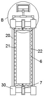
[0027] Embodiment 2: refer to Figure 3-5 , the difference in connection with the basis of Embodiment 1 is that the deformation mold 2 includes an outer template 20, a first module 21 and a second module 22, the first module 21 is fixedly installed on the left side of the outer template 20, and the second module 22 is fixed Installed on the right side of the outer formwork 20, the first module 21 and the second module 22 are engaged and connected, and the two sides of the first module 21 and the second module 22 are fixedly installed with the connecting assembly 6, and the first module 21 and the second module 22 pass through The connecting components 6 are movably connected with each other, corner pieces 30 are fixedly installed at the four corners of the outer template 20 , the adjusting arm 4 is fixedly connected with the corner pieces 30 , and hinges 7 are fixedly installed between the corner pieces 30 .
[0028] Adjusting arm 4 comprises main track 23, main slide block 24...
Embodiment 3
[0030] Embodiment 3: refer to Figure 6-7 The difference in connection with the basis of Embodiment 1 is that a connection groove 13 is provided on the outer surface of the cabinet 14, the main track 23 is movably connected with the connection groove 13, and the other end of the main track 23 is movably connected with the main control box 5 , the outer surface of the chassis 14 is also provided with a sealing groove 32, the sealing groove 32 matches the outer formwork 20, the four corners of the sealing groove 32 are fixedly installed with positioning columns 31, and the leftmost side of the outer formwork 20 is fixedly installed with a positioning buckle 12 , the positioning post 31 matches the positioning buckle 12 .
[0031] The upper surface of the main control box 5 is fixedly equipped with a main board 34, the inside of the main control box 5 is provided with a water storage chamber 33, and the bottom surface of the main control box 5 is fixedly equipped with a main valv...
PUM
 Abstract
Description
Claims
Application Information
 - R&D
- Intellectual Property
- Life Sciences
- Materials
- Tech Scout
- Unparalleled Data Quality
- Higher Quality Content
- 60% Fewer Hallucinations
Browse by: Latest US Patents, China's latest patents, Technical Efficacy Thesaurus, Application Domain, Technology Topic, Popular Technical Reports.
© 2025 PatSnap. All rights reserved.Legal|Privacy policy|Modern Slavery Act Transparency Statement|Sitemap|About US| Contact US: help@patsnap.com