
Pneumatic hot-press welding machine

A hot-pressing welding and pneumatic technology, applied in the field of pneumatic hot-pressing welding machines, can solve the problems of fatigue damage of parts, inconvenient maintenance of driving mode, large reaction force of mechanical parts, etc., to achieve small pressure damage and easy auxiliary fixation. The effect of placing the mold and the uniform force

Inactive Publication Date: 2019-04-02
上海恒特电子科技有限公司
View PDF4 Cites 0 Cited by
  • Summary
  • Abstract
  • Description
  • Claims
  • Application Information

AI Technical Summary

Problems solved by technology

[0003] In the prior art, conventional hot-press welding machines are driven by mechanical transmission such as electric telescopic mechanism or hydraulic mechanism. This driving method is generally used for vertical pressure in conventional processing. However, this method There is a problem of excessive reaction force on the mechanical parts when under pressure, which is easy to cause fatigue damage to the parts, and the conventional driving method is not easy to maintain

Method used

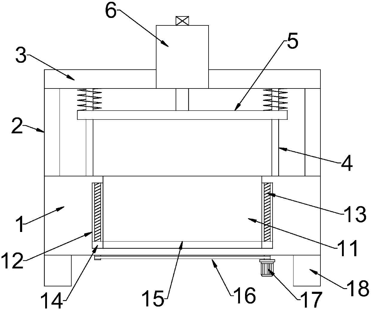

Image

  • Pneumatic hot-press welding machine
  • Pneumatic hot-press welding machine
  • Pneumatic hot-press welding machine

Examples


Embodiment 1

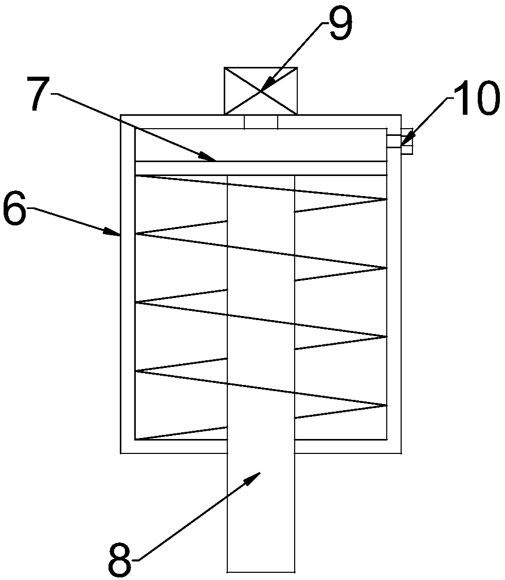
[0020] see Figure 1~2 , in an embodiment of the present invention, a pneumatic hot-press welding machine includes a supporting structure, a lifting structure, a driving structure 6 and a thermal welding head 5, and the supporting structure is symmetrically connected by a bracket 2 on both sides of the upper end of the base 1 to set a crossbeam 3 The middle part of the base 1 is embedded with a groove 11, and sliding grooves 12 are symmetrically embedded on both sides of the groove 11. A lifting structure is arranged between the sliding grooves 12, and a driving structure is arranged on the crossbeam 3. 6. A piston plate 7 is slidingly fitted in the driving structure 6, and the lower end of the piston plate 7 is elastically connected to the inner bottom of the driving structure 6 through a spring. The push rod 8 at the bottom of 6, the lower end of the push rod 8 is welded with a heat welding head 5, the two ends of the heat welding head 5 are symmetrically slid through and pr...

Embodiment 2

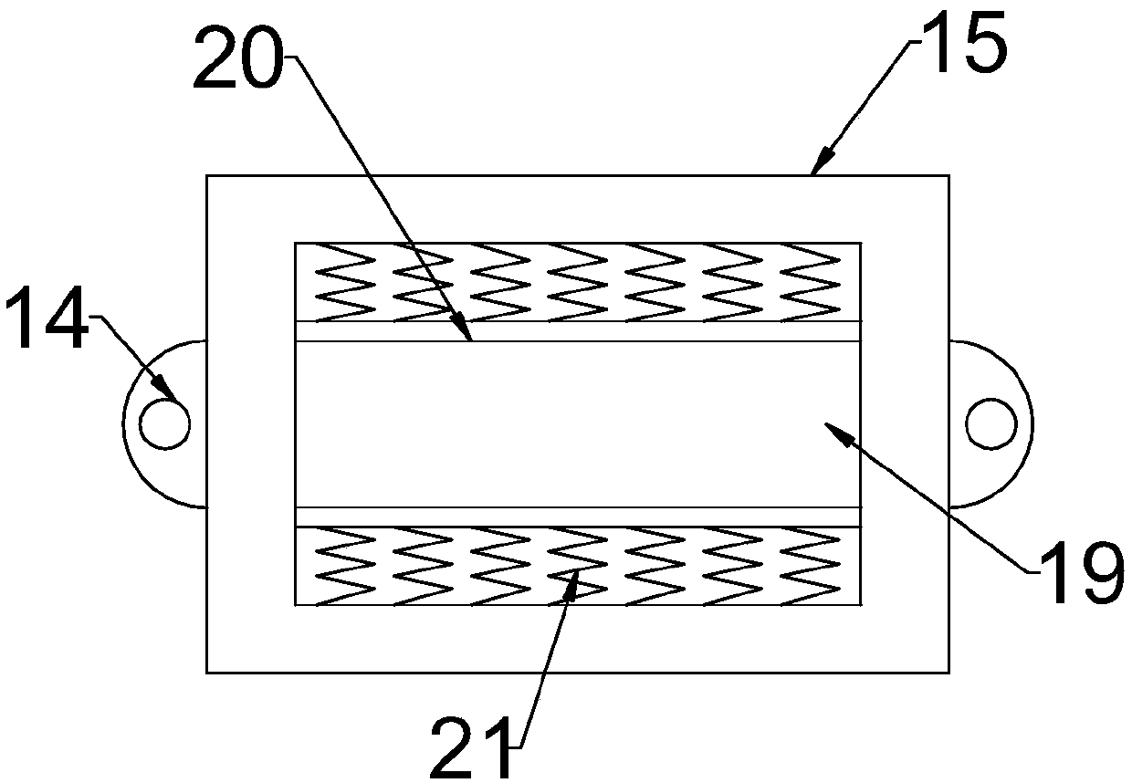
[0028] see image 3 , in the embodiment of the present invention, a pneumatic hot-press welding machine, on the basis of embodiment 1, the middle part of the upper end of the placement plate 15 is embedded with a placement groove 19, and the front and rear sides of the placement groove 19 are symmetrically passed through the clip The holding spring 21 is elastically connected with splints 20, and the opposite sides of the splints 20 on both sides are fitted with rubber pads.

[0029] In this way, it is convenient to assist in fixing and placing the mold, improve stability, facilitate alignment, and force more uniformly during processing, thereby ensuring the processing effect.

[0030] The working principle of the present invention is: when in use, the mold is placed between the splints 20 in the placement groove 19, which is convenient for auxiliary fixing and placement of the mold, improves stability, facilitates alignment, and the force is more uniform during the processing...


PUM


Abstract

The invention discloses a pneumatic hot-press welding machine which comprises a supporting structure, a lifting structure, a driving structure and a heat welding head. The supporting structure is formed in the manner that a transverse beam is arranged on the two sides of the upper end of a base through supports symmetrically in a connected manner, a groove is embedded in the middle of the base, sliding grooves are symmetrically embedded in the two sides of the groove, the lifting structure is arranged between the sliding grooves, the driving structure is arranged on the transverse beam, a piston plate is arranged in the driving structure in a sliding fit manner, the lower end of the piston plate is elastically connected with the inner bottom of the driving structure through a spring, a push rod movably penetrating the bottom of the driving structure is welded to the lower end of the piston plate, the heat welding head is welded to the lower end of the push rod, sliding rods symmetrically penetrate through the two ends of the heat welding head in a sliding manner, an air pump is arranged at the upper end of the driving structure in a communicating manner, and a containing plate matched with the groove in size and opposite to the heat welding head is arranged on the lifting structure in a connecting manner. According to the pneumatic hot-press welding machine, the lifting structure is designed, and movable adjustment and processing are facilitated according to the thickness of a mold; and the processing effect is improved through a pneumatic manner, and the durability effectof all components is improved.

Description

technical field [0001] The invention relates to the field of hot-press welding machines, in particular to a pneumatic hot-press welding machine. Background technique [0002] Thermocompression welding machine is a kind of welding machine that welds plastic film to plastic shell or another plastic film. The plastic film is welded to the plastic shell through the hot welding head, which has the advantages of fast processing speed and good welding quality. [0003] In the prior art, conventional hot-press welding machines are driven by mechanical transmission such as electric telescopic mechanism or hydraulic mechanism. This driving method is generally used for vertical pressure in conventional processing. However, this method There is a problem that the reaction force to the mechanical parts is too large when under pressure, which is easy to cause fatigue damage to the parts, and the conventional driving method is not easy to maintain. Contents of the invention [0004] The...

Claims


Application Information

Patent Timeline
IPC IPC(8): B29C65/02
CPCB29C65/02
Inventor 王玲何兰海周顺华刘毅梁全祖
Owner 上海恒特电子科技有限公司
Learn More