
Energy-saving liquid cooling system

A liquid-cooled, energy-efficient technology

Inactive Publication Date: 2019-04-02
XIAN AIRCRAFT DESIGN INST OF AVIATION IND OF CHINA
View PDF8 Cites 4 Cited by
  • Summary
  • Abstract
  • Description
  • Claims
  • Application Information

AI Technical Summary

Problems solved by technology

[0003] The purpose of the present invention is to provide a fast-response energy-saving liquid cooling system to solve the technical problem that the liquid cooling system is difficult to start at low temperature

Method used


Image

  • Energy-saving liquid cooling system
  • Energy-saving liquid cooling system

Examples


Embodiment Construction

[0017] The energy-saving liquid cooling system of the present invention will be further described below in conjunction with the accompanying drawings and embodiments:

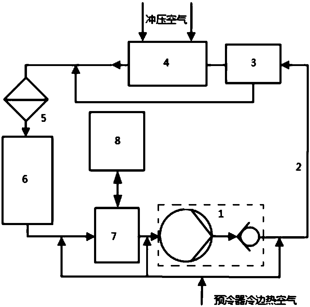
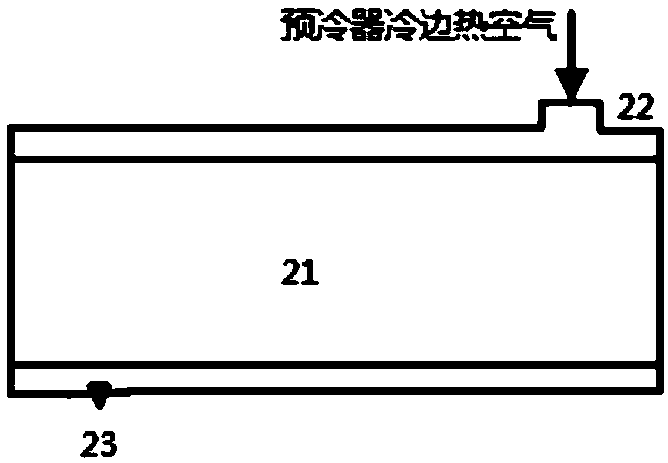
[0018] The energy-saving liquid cooling system of the present invention includes: a liquid pump assembly 1, a liquid cooling pipeline 2, a temperature regulating valve 3, an air-liquid heat exchanger 4, a filter 5, an electronic device 6, a gas-liquid separator 7, a booster expansion device 8; the liquid cooling pipeline 2 has an inner channel and an outer channel, and the outer channel has a hot air intake joint 22 and an exhaust one-way device 23; when the liquid cooling pipeline 2 system is started at low temperature, the environment The hot air from the outlet of the cold side of the pre-cooler of the control system enters the outer channel with the air interlayer liquid cooling pipeline 2 to heat the cooling liquid 21 in the inner channel. The cooling liquid 21 is filtered through the filter 5 before passi...


PUM


Abstract

The invention relates to an energy-saving liquid cooling system, which mainly comprises a liquid pump assembly (1), a liquid cooling pipeline (2), a temperature regulating valve (3), an air-liquid heat exchanger (4), a filter (5), an electronic device (6), a gas-liquid separator (7) and a pressurizing expansion device (8). The liquid cooling pipeline (2) is provided with an inner passage and an out passage, the outer passage is provided with a hot air intake joint (22) and an exhaust unidirectional device (23); when the liquid cooling pipeline (2) system is started at a low temperature, hot air at the cold side outlet of a precooler of an environmental control system enters the outer passage of the liquid cooling pipeline (2) with an air sandwich, to heat a coolant (21) in the inner passage. The system collects the cold side exhaust gas of the precooler, utilizes the part of heat to solve the problem that the liquid cooling system is difficult to start at a low temperature, reduces theelectric power demand of the liquid cooling system, and reduces the compensation loss of an aircraft.

Description

technical field [0001] The invention belongs to the technical field of aircraft environment control, and relates to an energy-saving liquid cooling system, in particular to a fast-response energy-saving liquid cooling system. Background technique [0002] No. 65 coolant is generally used as the cooling medium in traditional aircraft liquid cooling systems. The viscosity of No. 65 coolant increases significantly when the temperature is lower than 0°C, especially when the temperature is lower than -40°C, the viscosity increases sharply. To solve this problem, the system usually installs an electric heating device to heat the coolant. If a low-power electric heating device is installed in the system, there will be a problem of long heating time. problem of large losses. In addition, when the liquid pump in the system is started at low temperature, there will be problems such as failure to start, failure to start, and reduced reliability. On the other hand, the exhaust tempera...

Claims


Application Information

Patent Timeline
Patent Type & Authority Applications(China)
IPC IPC(8): B64D13/06
CPCB64D13/06B64D2013/0603Y02T50/50
Inventor 马兰李艳娜齐社红
Owner XIAN AIRCRAFT DESIGN INST OF AVIATION IND OF CHINA
Learn More