Water treatment device capable of generating functional water, application method and water treatment method

A water conduction and water body technology, applied in water/sewage treatment, water/sewage multi-stage treatment, water/sludge/sewage treatment, etc., can solve the problem of inconsistent level of functional material consumption, unreasonable structure, and troublesome filter material replacement. and other problems, to achieve the effect of simple structure, delayed dissolution and diffusion, and convenient addition

Pending Publication Date: 2019-04-02
FUZHOU PINXING TECH DEV
5 Cites 0 Cited by

AI-Extracted Technical Summary

Problems solved by technology

However, the current water guides on the market are equipped with multiple functional materials at the same time in a single tube. Due to the unreasonable structure, the wear and tear of various f...

Method used

Described filter assembly comprises filter material structure 500 and filter core structure 510; Filter material accommodation unit and filter core accommodation unit are included in a plurality of filter element holding units; Filter material structure 500, filter core structure 510 are installed in filter material holding unit respectively , In the filter housing unit. The filter core structure 510 includes a support tube 512 and a honeycomb ceramic filter core 511 ; a plurality of honeycomb ceramic filter cores 511 are arranged along the axial direction of the support tube 512 . As shown in Figure 1, the filter element structure 510 is a pre-assembled structure, and the support tube 512 is fastened with an attachment plate 513. After the honeycomb ceramic filter element 511 penetrates along the axial end of the support tube 512, the attachment plate 513 forms a pair of Limitation of penetration depth of ceramic filter element 511 and final fixation. Preferably, the support pipe 512 comprises ABS pipe. On the basis of the above structure, it is also easy to realize partial communication or non-communication among multiple filter storage units, for example, a sealing plate structure is connected to the support pipe 512 . The significance of the partial connection or non-communication of the filter housing units is that the filter holes 112 on the water guide cylinder 100 can be unevenly distributed, so that the effect of dissolving the filter material particles into the water in different filter housing units is different, so as to adapt to the differences. In addition, there may be differences in the service life and the number of cycles between different filter material particles. Through the disconnected structure, it is convenient to separate and replace the filter material particles separately.
Taking the water guiding device provided by the present invention as an example, the water guiding device is placed in the cup body 300 equipped with a water body, and the pure water obtained by the honeycomb ceramic filter element 511 from the treatment of the water body passes through the permanent magnet parts on the cylinder cover structure 200 213 magnetization treatment to achieve magnetization antibacterial and sterilization, resist high hardness water quality, improve water penetration, solubility and other physical changes of magnetized water. At the same time, let the pure water fully contact with the solid filter material particles, resulting in the contact between particles and water, the collision between particles, and more importantly, the interaction between particles and stainless steel wire mesh 113, such as bumping and scraping, so that the water guides the cylinder 100 The condition that promotes the slow dissolution of the filter material due to the interaction between the filter material and water is generated, and the mechanism of ...

Abstract

The present invention provides a water treatment device capable of generating functional water, an application method and a water treatment method. The water treatment device comprises a water treatment cylinder body, the interior of the water treatment cylinder body is provided with an accommodating cavity body, and the inner space of the accommodating cavity body forms an accommodating space; the accommodating space includes one or more filter-element accommodating units; when there are a plurality of filter-element accommodating units, the plurality of filter-element accommodating units areconnected with each other, partially connected with each other or not connected with each other; two ends of the water treatment cylinder body along an axial direction respectively form a first end portion and a second end portion, and the accommodating space communicates with outer space of the water treatment cylinder body through an end surface opening of the first end portion and/or an end surface opening of the second end portion; and the end surface openings are provided with cylinder covers, and filter assemblies are arranged in the filter-element accommodating units. The water treatment device of the invention has a simple structure, is convenient for replacement, cleaning and filter core material addition, reduces waste, and greatly reduces the cost of a user for treating water into functional water.

Application Domain

Technology Topic

Image

  • Water treatment device capable of generating functional water, application method and water treatment method
  • Water treatment device capable of generating functional water, application method and water treatment method

Examples

  • Experimental program(1)

Example Embodiment

[0058] The present invention will be described in detail below in conjunction with specific embodiments. The following examples will help those skilled in the art to further understand the present invention, but do not limit the present invention in any form. It should be pointed out that for those of ordinary skill in the art, a number of modifications and improvements can be made without departing from the concept of the present invention. These all belong to the protection scope of the present invention.
[0059] In the description of the present invention, it should be understood that the terms "upper", "lower", "front", "rear", "left", "right", "vertical", "horizontal", "top", The orientation or positional relationship indicated by "bottom", "inner", "outer", etc. are based on the orientation or positional relationship shown in the drawings, which is only for the convenience of describing the present invention and simplifying the description, and does not indicate or imply the pointed device Or the element must have a specific orientation, be constructed and operated in a specific orientation, and therefore cannot be understood as a limitation of the present invention.
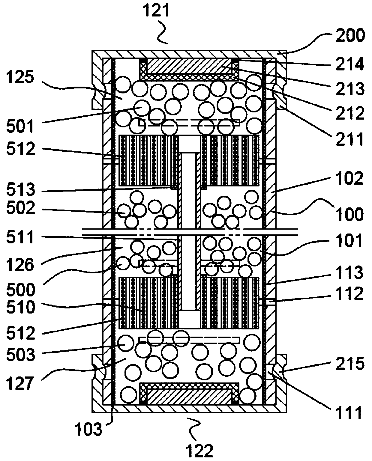
[0060] Such as figure 1 As shown, the water guiding device provided by the present invention includes a water guiding cylinder 100, an accommodating cavity is formed inside the water guiding cylinder 100, and the inner space of the accommodating cavity forms an accommodating space 101; the accommodating space 101 contains One or more filter accommodating units; when there are multiple filter accommodating units, the plurality of filter accommodating units communicate with each other, partially communicate or not; the two ends of the water guide cylinder 100 in the axial direction respectively form the first The one end 121, the second end 122, and the accommodating space 101 are connected to the outer space of the water guide cylinder 100 through the end surface openings on the first end 121 and/or the end surface openings of the second end 122; End face opening position (e.g. figure 1 The central axis end opening 103 position) is equipped with a cylinder cover structure 200, the cylinder cover structure 200 and the water guide cylinder 100 are detachably connected, hinged or sliding connection, the cylinder cover structure 200 can be in both the open state and the closed state Conversion between the two states: in the open state, the cylinder cover structure 200 forms an opening to the shaft end opening 103; in the closed state, the cylinder cover structure 200 forms a closure to the shaft end opening 103. In other words, the cylinder cover structure 200 can be opened or closed by disassembling, rotating or sliding. When in the closed state, the filter material 403 placed in the filter material storage space will not be able to open the hole 103 from the shaft end. Pour it out for practical use; when it is in the open state, the filter material 403 can be put in or taken out from the opening 103 at the shaft end. The filter accommodating unit is provided with a filter assembly.
[0061] The water-conducting cylinder 100 includes a peripheral wall 102, which is a circumferential wall surface of the water-conducting cylinder 100, that is, a structural member that encloses the containing cavity. A scraping structure is provided on the inner wall surface of the peripheral wall 102; the filter assembly can contact the scraping structure. In an embodiment, the scraping structure includes a stainless steel wire mesh 113; the stainless steel wire mesh 113 is laid on the inner wall surface of the peripheral wall 102 conformally. The peripheral wall 102 of the water guide cylinder 100 is provided with a filter hole 112, and the accommodation space 101 is also communicated with the outer space of the water guide cylinder 100 through the filter hole 112. The plurality of filter holes 112 are arranged along the axial and/or circumferential direction of the water guide cylinder 100. In practical applications, the filter assembly may contain filter material particles, and the width of the filter holes 112 is smaller than the minimum diameter of the filter material particles; or, the stainless steel wire mesh 113 covers the filter holes 112 on the extension surface, and the stainless steel wire mesh 113 The mesh diameter is smaller than the smallest diameter of the filter material particles. The arrangement rule of the plurality of filter holes 112 on the peripheral wall 102 can be selected according to needs. The shape of the filter holes 112 can be a hole shape, or a linear belt-like or arc-belt-like structure. The setting of the stainless steel wire mesh 113 is mainly to increase the scraping with the filter material particles, so that the water conduction produces the interaction between the filter material and water to delay dissolution and diffusion; preferably, the inner wall surface of the peripheral wall 102 of the water conduction cylinder 100 A contact protrusion is provided, and the contact protrusion may be a bump structure or a rib structure. The contact protrusion is a replacement part of the stainless steel wire mesh 113, or is provided at the same time as the stainless steel wire mesh 113, which can also increase the impact and scratching effect. The stainless steel wire mesh 113 itself has a certain mesh, therefore, it can also prevent the filter material particles from leaking from the filter material placement space along the filter hole 112, which reduces the size setting requirements of the filter hole 112, that is, the filter hole 112 The width can be larger, so that the water and the filter material particles are fully and efficiently contacted.
[0062] The cylinder cover structure 200 is provided with a concave card 215; the peripheral wall 102 of the water guide cylinder 100 is provided with a bayonet 111; the concave card 215 matches the bayonet 111; the cylinder cover structure 200 is in the closed state, The card 215 is locked into the bayonet 111 by the elastic force of the cylinder cover structure 200. Preferably, the concave card 215 is provided on the cylinder cover body 211; preferably, the bayonet 111 has a through hole structure or a blind hole structure, that is, the peripheral wall 102 of the water guiding cylinder 100 only needs to exist The matching structure used for buckling and sealing the cylinder cover structure 200 is sufficient. Further preferably, the cylinder cover structure 200 and the water guide cylinder body 100 may be detachably connected through a structure such as a sealed thread.
[0063] In an embodiment, the cylinder cover structure 200 includes a cylinder cover body 211 and an attachment box body 212, the cylinder cover body 211 and the attachment box body 212 are firmly connected to form a container space inside; the container space is provided with water Guide function parts. Preferably, the attachment box body 212 includes an ABS plastic box, and the ABS plastic box and the cylinder cover body 211 are glued together by a waterproof adhesive layer 214; the water guiding function component includes a permanent magnet component 213. Through the above structure, the permanent magnet 213 can be prevented from contacting the water body, which can magnetize the water without polluting the water body. Preferably, the water guide cylinder 100 or the cylinder cover body 211 comprises a food-grade stainless steel material or a food-grade polymer material. Preferably, the water-conducting functional component may also be other structures, such as hydrogen production equipment.
[0064] The filter assembly includes a filter material structure 500 and a filter element structure 510; a plurality of filter element accommodation units includes a filter material accommodation unit and a filter element accommodation unit; the filter material structure 500 and the filter element structure 510 are respectively installed in the filter material accommodation unit and the filter element accommodation unit Unit. The filter element structure 510 includes a support tube 512 and a honeycomb ceramic filter element 511; a plurality of honeycomb ceramic filter elements 511 are arranged along the axial direction of the support tube 512. Such as figure 1 As shown, the filter element structure 510 is a pre-assembled structure. The support tube 512 is fastened with an attachment plate 513. After the honeycomb ceramic filter element 511 is inserted along the axial end of the support tube 512, the attachment plate 513 forms a pair of the honeycomb ceramic filter element 511. Limitation of penetration depth and final fixation. Preferably, the support tube 512 includes an ABS tube. On the basis of the above-mentioned structure, it is also easy to realize partial communication and disconnection between a plurality of filter accommodating units, for example, a sealing plate structure is connected to the support tube 512. The meaning of partial connection or disconnection of the filter accommodating unit is that the filter holes 112 on the water guide cylinder 100 can be distributed unevenly, so that the effect of the filter material particles in the water in different filter accommodating units is different, so as to adapt to the difference. In addition, there may be differences in the service life and the number of cycles between different filter particles. The disconnected structure facilitates the separation and individual replacement of filter particles.
[0065] After the filter element structure 510 is installed in the filter element accommodating unit, it forms a boundary dividing the multiple filter material accommodating units; the multiple filter material accommodating units include any one or more of the following contents: the first accommodating unit 125: located Between the end surface of the first end 121 of the water guide cylinder 100 and the filter element structure 510; the second containing unit 126: located between the two adjacent honeycomb ceramic filter elements 511 in the filter element structure 510; the third containing unit 127: located Between the end surface of the second end 122 of the water guide cylinder 100 and the filter element structure 510.
[0066] In a preferred embodiment, the first containment unit 125, the second containment unit 126, and the third containment unit 127 are respectively filled with a first filter material 501, a second filter material 502, and a third filter material 503. Among them, the first filter material 501 contains zinc, copper, and magnesium according to a certain weight ratio through high temperature melting A metal material; the second filter material 502 contains granular magnesium with a diameter of 1 to 5 mm; the third filter material 503 contains tourmaline, Purified ore and clay are the main sintered mineral materials.
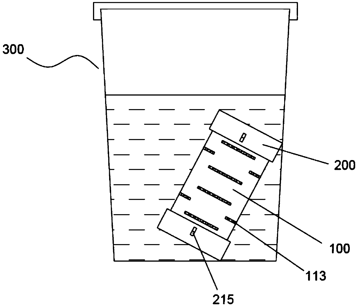
[0067] The present invention also provides an application method of the above-mentioned water guiding device, including the following steps: Step S1: disassembling the water guiding cylinder 100 and the cover structure 200, and putting the filter element structure 510 included in the filter assembly into the containing space 101 In the remaining space of the accommodating space 101, the filter material structure 500 included in the filter assembly is filled; Step S2: After assembling the water guide cylinder 100 and the cover structure 200, they are placed in a water container, so that the water body passes through the water guide. The filter hole 112 of the cylinder 100 is in contact with the filter assembly; Step S3: Shake the water container so that the particles contained in the filter structure 500 collide with each other, and the particles collide with the stainless steel wire mesh on the inner wall surface of the peripheral wall 102 of the water guide cylinder 100 113 collision and scratching occurred.
[0068] Such as figure 2 As shown, in the embodiment, the water container includes a cup body 300. The actual operation is that the original vacant water guide cylinder 100 can be used to force a cylinder cover structure 200 to pry open, so that the concave card 215 of the cylinder cover structure 200 is separated from the buckle 111 of the water guide cylinder 100, and the cylinder cover structure can be pulled out 200. The stainless steel wire mesh 113 with micropores is arranged in a cylindrical shape and is tightly sleeved on the inner wall surface of the peripheral wall 103 of the water guide cylinder 100; then the honeycomb ceramic filter element 511 is inserted and supported by the ABS tube and placed on the stainless steel wire In the middle of the mesh 113, different appropriate amounts of the first filter material 501, the second filter material 502, and the third filter material 503 are filled in the gap between the stainless steel wire mesh 113 and the honeycomb ceramic filter element 511. It is best not to install it. Too full. By restoring and installing the above-mentioned cylinder cover structure 200, the full water-conducting cylinder 100 can be put into the cup 300 containing the water body, and the water body can pass through the filter hole 112 of the water-conducting cylinder 100 to contact the filter material particles. If the charged water guide cylinder 100 is only submerged in the water of the cup 300, the filter material particles produced by the sintering process are difficult to dissolve in a short time, and the water treatment effect will not be produced. During this process, shake the cup body 300 vigorously several times to drink the pure water in the cup (the pure water treated by the reverse osmosis process is the best choice). At this time, the pure water shaking in the cup is magnetized by the permanent magnet 213 on the cylinder cover structure 200 to achieve magnetization, bacteriostasis and sterilization, resistance to high-hardness water, and improved water penetration, solubility, and other physical changes. ; At the same time, let the pure water fully contact the solid filter material particles, resulting in particle-water contact, particle-particle collisions, and more importantly, the interaction between particles and the stainless steel cylinder wall, such as collision and scratching, and more importantly The interaction between the particles and the stainless steel wire mesh 113, such as scraping, allows the water conduction to produce conditions that promote the slow dissolution of the filter material due to the interaction between the filter material and water, and form the mechanism of slow release and long-term diffusion of the filter material under this condition, thereby making the water body It is further purified, activated, mineralized, added with beneficial minerals, and healthy water formed by dissolving a variety of beneficial minerals. When you need to replace, clean or add filter media, you can repeat the steps according to the above principles.
[0069] The present invention also provides a water treatment method, which simultaneously performs the following steps through the same water guiding device: filter material dissolving step: making the filter material structure 500 blend into the water body; filter element filtering step: making the filter element structure 510 filter the water body; Magnetization step: magnetize the water body.
[0070] Taking the water guiding device provided by the present invention as an example, the water guiding device is placed in a cup 300 containing a water body, and the purified water obtained by the honeycomb ceramic filter element 511 on the water body is magnetized by the permanent magnet 213 on the cylinder cover structure 200 Treatment to achieve magnetized water with physical changes such as magnetization, bacteriostasis and sterilization, resistance to high-hardness water quality, and improvement of water penetration and solubility. At the same time, let the pure water fully contact the solid filter material particles, resulting in particle-water contact, particle-particle collisions, and more importantly, the interaction between the particles and the stainless steel wire mesh 113, such as collision and scratching, so that the water guides the cylinder. 100 produces conditions that promote the slow dissolution of the filter material due to the interaction between the filter material and water, and produce the mechanism of slow release and long-term diffusion of the filter material particles under this condition, so that the water body can be further purified, magnetized, activated, and mineralized. Added beneficial minerals and healthy water formed by dissolving a variety of beneficial minerals.

PUM

no PUM

Description & Claims & Application Information

We can also present the details of the Description, Claims and Application information to help users get a comprehensive understanding of the technical details of the patent, such as background art, summary of invention, brief description of drawings, description of embodiments, and other original content. On the other hand, users can also determine the specific scope of protection of the technology through the list of claims; as well as understand the changes in the life cycle of the technology with the presentation of the patent timeline. Login to view more.

Similar technology patents

Classification and recommendation of technical efficacy words

  • Simple structure
  • Easy to add

Beam expanding optical element, beam expansion method, image display apparatus, and head-mounted display

InactiveUS20070188837A1Reduce color unevennessSimple structureOptical light guidesSubstrate with hologramHead worn displayLight wave
Owner:KONICA MINOLTA INC

Microlithographic projection exposure apparatus

InactiveUS20050068499A1Simple structureReliable and low-maintenance operationProjectorsPhotomechanical exposure apparatusCamera lensPhysics
Owner:CARL ZEISS SMT GMBH

Information distribution system

InactiveUS6148301AReducing and shortcoming and disadvantageEasy to addData processing applicationsDatabase distribution/replicationDistribution systemCentralized database
Owner:FIRST DATA
Why Eureka
Try Eureka