
LED factory lamp with air channel optimized through fin group applied to normal temperature state

A technology for LED factory lights and fin sets, which is applied in the direction of cleaning methods using tools, chemical instruments and methods, cleaning methods and utensils, etc., can solve the discount of heat dissipation effect, the deterioration of heat dissipation effect, and the impact on the service life of LED factory lights, etc. problems, to achieve the effect of keeping clean, prolonging service life and good heat dissipation

Pending Publication Date: 2019-04-02
江苏新西贝机电有限公司
View PDF2 Cites 2 Cited by
  • Summary
  • Abstract
  • Description
  • Claims
  • Application Information

AI Technical Summary

Problems solved by technology

[0007] However, in some factories with a lot of dust, the dust floating around will adhere to the lamp holder of the LED factory lamp. After the heat sink and other structural surfaces on the surface of the lamp holder are covered by thick dust, the heat dissipation effect will be greater. Discount, poor cooling effect will seriously affect the service life of LED factory lights

Method used


Image

  • LED factory lamp with air channel optimized through fin group applied to normal temperature state
  • LED factory lamp with air channel optimized through fin group applied to normal temperature state
  • LED factory lamp with air channel optimized through fin group applied to normal temperature state

Examples


Embodiment 1

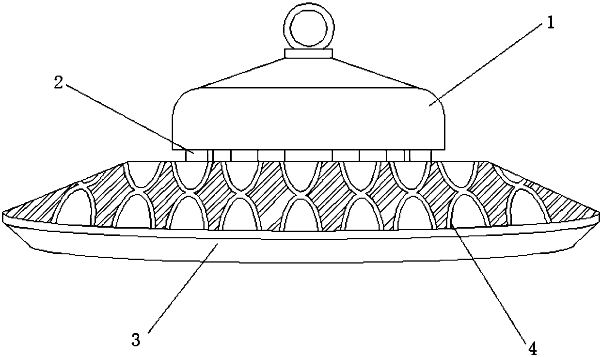
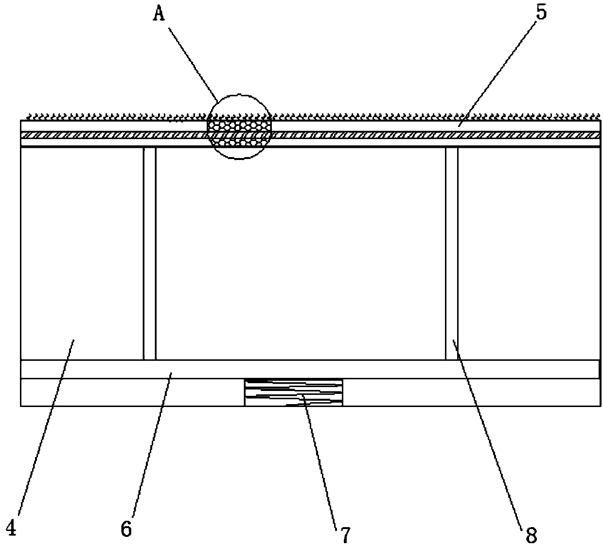
[0043] see figure 1 , a fin group optimized air duct type LED factory light applied at normal temperature, including a lamp holder 3 connected to the lower end of the mounting base 1 through a connecting column 2, and a lamp bead is installed inside the lamp holder 3, and the high temperature resistance of 150 degrees Celsius is selected The Philips LED lamp bead, model: LUXEOMHR30, increases the number of lamp bead particles, reduces the power of a single lamp bead, ensures that the lamp bead will not cause light decay due to continuous high temperature, and effectively guarantees the service life of the entire lamp; the upper end of the lamp holder 3 is set There is an air duct, the air duct includes cooling fins 4, and the cooling fins 4 are fixedly connected to the surface of the lamp holder 3, please refer to figure 2 , both sides of the radiating fin 4 are equipped with a temperature-variable dust removal mechanism, the temperature-variable dust-removal mechanism includ...


PUM

PropertyMeasurementUnit
Elongation lengthaaaaaaaaaa
Lengthaaaaaaaaaa

Abstract

The invention discloses an LED factory lamp with an air channel optimized through a fin group applied to the normal temperature state, and belongs to the field of LED factory lamps. The LED factory lamp with the air channel optimized through the fin group applied to the normal temperature state comprises a lamp holder connected to the lower end of a mounting base through a connecting post, a lampbead is mounted inside the lamp holder, the air channel is arranged at the upper end of the lamp holder, the air channel comprises cooling fins, temperature variation type dust collecting mechanisms are arranged on two sides of the cooling fins, and each temperature variation type dust collecting mechanism comprises a dust collecting net, a specially-shaped dust collecting movable plate and a temperature variation rod. According to the technical scheme, the surface of the lamp holder is arranged to be the fin group, so that the cooling air channel of the lamp body is optimized, in addition, the temperature variation type dust collecting mechanisms are arranged on the surfaces of the cooling fins in the fin group from, the temperature variation type dust collecting mechanisms can be used for carrying out automatic dust colleting on the surfaces of the cooling fins during the work process of the LED factory lamp, so that the cleanness of the surfaces of the cooling fins is maintained, therefore, the good cooling effect of the cooling fins is guaranteed, and further, the service life of the LED factory lamp is prolonged.

Description

technical field [0001] The invention relates to the field of LED factory lamps, more specifically, relates to a fin group optimized air duct type LED factory lamp applied at normal temperature. Background technique [0002] LED (Light Emitting Diode), light-emitting diode, is a solid-state semiconductor device that can convert electrical energy into visible light, and it can directly convert electricity into light. The heart of LED is the wafer of a semiconductor, and one end of wafer is attached on a bracket, and one end is negative pole, and the other end connects the positive pole of power supply, and whole wafer is encapsulated by epoxy resin. [0003] Semiconductor wafer is made up of two parts, and a part is P-type semiconductor, and hole occupies an leading position in it, and the other end is N-type semiconductor, and here mainly is electron. But time these two kinds of semiconductors couple together, between them, just form a P-N junction. When electric current ac...

Claims


Application Information

Patent Timeline
IPC IPC(8): F21S8/00F21V29/74B08B1/00F21Y115/10
CPCF21S8/00F21V29/74F21Y2115/10B08B1/30
Inventor 贾仕
Owner 江苏新西贝机电有限公司
Learn More