Fly ash conveying system for garbage incinerator

A waste incinerator and conveying system technology, which is applied in the field of waste incineration power plant furnace system, can solve the problems of waste incineration power generation system not running normally, high equipment operating costs, and small gaps

Pending Publication Date: 2019-04-02
SHENZHEN ENERGY ENVIRONMENT ENG
View PDF0 Cites 4 Cited by
  • Summary
  • Abstract
  • Description
  • Claims
  • Application Information

AI Technical Summary

Problems solved by technology

Due to the complex structure of the water-cooled screw ash conveyor with heat exchange surfaces, the rotating mechanism of the system is huge and complex, and the copper joints of the rotating water pipes of the water-cooled screw ash conveyor are prone to water leakage. Ash valves are rotating equipment with complex structures
During operation, the system is prone to fly ash accumulation jamming, resulting in jamming of rotating parts, motor overload, leakage of heating surface, water leakage of copper joints of rotating water pipes, etc.
System mainten

Method used


Image

  • Fly ash conveying system for garbage incinerator
  • Fly ash conveying system for garbage incinerator
  • Fly ash conveying system for garbage incinerator

Examples


Embodiment Construction

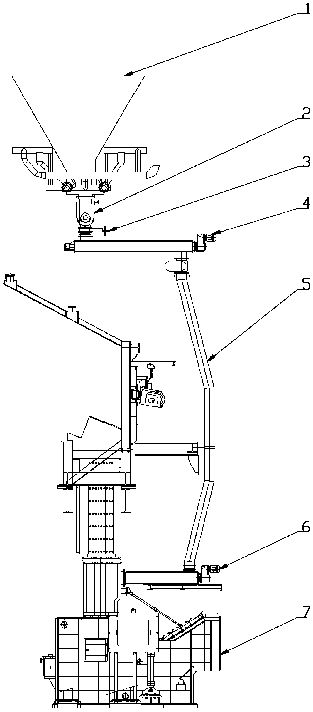
[0031] figure 1 It is a structural schematic diagram of an embodiment of the prior art. The figure shows that in the prior art, the waste incinerator fly ash conveying system mainly includes an ash collecting bucket 1, a water-cooled screw ash conveyor 2, a rotary ash unloading valve 3, a removal screw ash conveyor 4, an ash drop pipe 5, Advance the screw ash conveyor 6, the slag removal machine 7 and the slag removal pool; the fly ash falls into the ash collection hopper 1 through inertial capture, and then enters the rotary ash discharge valve 3 after passing through the water-cooled screw ash conveyor 2, and then enters the Remove the ash conveying screw 4, and finally enter the ash conveying screw 6 through the ash pipe 5. Because the components of the complex structure of the water-cooled ash conveyor 2 include heat exchange surfaces, the system rotation mechanism is large and complex, and the copper joints of the rotating water pipes of the water-cooled ash conveyor 2 a...


PUM


Abstract

The invention provides a fly ash conveying system for a garbage incinerator. The fly ash conveying system for the garbage incinerator comprises an ash collecting hopper, a front ash pipe, a rear ash pipe, a working ash falling pipe, a slag catching machine and a slag catching pool in sequence from top to bottom according to the conveying direction of fly ash. The fly ash falls into the ash collecting hopper, the front ash pipe, the rear ash pipe and the working ash falling pipe in sequence from top to bottom, then enters the slag catching machine and is finally conveyed to the slag catching pool. A J-shaped valve is arranged at the connecting corner of the front ash pipe and the rear ash pipe, and a normally-opened ash pipe valve is arranged at the connecting corner of the rear ash pipe and the working ash falling pipe. A first air distribution pipe is arranged in the J-shaped valve, a second air distribution pipe is arranged at the front end of the normally-opened ash pipe valve, a plurality of air outlet small holes are separately formed in the first air distribution pipe and the second air distribution pipe, and a compressed air conveying pipeline connected with the air distribution pipes is further arranged. When fly ash accumulation occurs at the corner, compressed air is separately conveyed to the first air distribution pipe and the second air distribution pipe through the compressed air conveying pipe and is sprayed out from each air outlet small hole to blow away the accumulated fly ash, so that the fly ash falls into the ash pipes to play the role of ash removal.

Description

technical field [0001] The invention relates to a furnace system of a waste incineration power plant, in particular to a waste incinerator fly ash conveying system. Background technique [0002] At present, the fly ash conveying system of waste incinerator mainly includes ash collection hopper, water-cooled screw ash conveyor, rotary ash unloading valve, removal screw ash conveyor, propulsion screw ash conveyor, slag extractor and slag extractor pool; fly ash After falling into the ash collecting hopper through inertial capture, after passing through the water-cooled screw ash conveyor, it enters the rotary ash unloading valve, then enters the removal screw ash conveyor, and finally enters the propulsion screw ash conveyor through the ash lowering pipe. Due to the complex structure of the water-cooled screw ash conveyor with heat exchange surfaces, the rotating mechanism of the system is huge and complex, and the copper joints of the rotating water pipes of the water-cooled ...

Claims


Application Information

Patent Timeline
IPC IPC(8): F23G5/44F23J3/00
CPCF23G5/44F23J3/00
Inventor 殷得文宋晨
Owner SHENZHEN ENERGY ENVIRONMENT ENG
Why Eureka
Try Eureka