
Air conditioner

An air conditioner and controller technology, applied in space heating and ventilation, heating methods, lighting and heating equipment, etc., can solve the problems of inconspicuousness, reduction of compressor pressure ratio, and affecting the cooling of air conditioners

Inactive Publication Date: 2019-04-02
QINGDAO HAIER AIR CONDITIONING ELECTRONICS CO LTD
View PDF8 Cites 7 Cited by
  • Summary
  • Abstract
  • Description
  • Claims
  • Application Information

AI Technical Summary

Problems solved by technology

When the ambient temperature of the condenser is low, due to the problem of pressure difference, the refrigerant after heat exchange in the condenser cannot flow back into the compressor, and the situation of "insufficient liquid supply" of the compressor will occur, resulting in the failure of the compressor. The pressure ratio decreases, which will cause the temperature of the internal motor and frequency converter to rise. When the temperature of the components reaches a certain value, the compressor will be forced to enter the unloading command, resulting in a decrease in cooling capacity, affecting the normal use of the user, and when the frequency converter's The compressor will even stop working when the temperature exceeds the set value
[0003] In view of the above problems, in the prior art, the start and stop of the cooling tower fan is manually controlled in order to reduce the temperature drop of the cooling water in the condenser when the outside temperature is low, but this method is time-consuming and laborious and the improvement effect is not obvious
In the prior art, the pressure ratio is increased by controlling the flow of chilled water and cooling water, or by controlling the maximum speed of the compressor to reduce the calorific value of the frequency converter and the motor, but obviously all of these will affect the cooling performance of the air conditioner.

Method used


Image

  • Air conditioner
  • Air conditioner
  • Air conditioner

Examples


Embodiment Construction

[0033] Preferred embodiments of the present invention are described below with reference to the accompanying drawings. Those skilled in the art should understand that these embodiments are only used to explain the technical principles of the present invention, and are not intended to limit the protection scope of the present invention. For example, although the following embodiments are explained in conjunction with a magnetic levitation chiller, this is not limiting, and the technical solution of the present invention is also applicable to other types of air conditioners, such as those using scroll compressors For air conditioners and the like facing the problem of low pressure ratio operation, this change of application object does not deviate from the principle and scope of the present invention.

[0034] It should be noted that, in the description of the present invention, terms such as "inner", "outer" and other indicated directions or positional relationships are based o...


PUM


Abstract

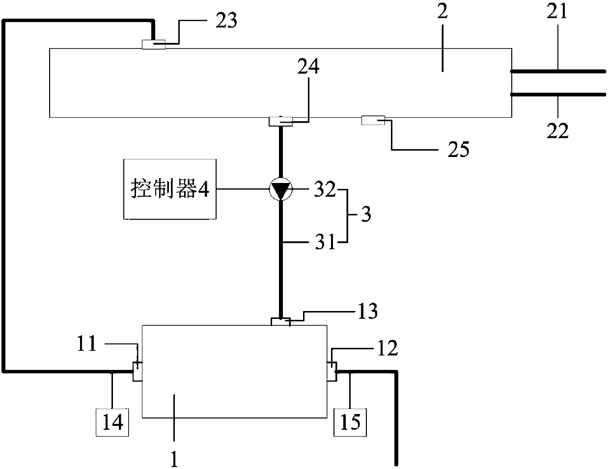
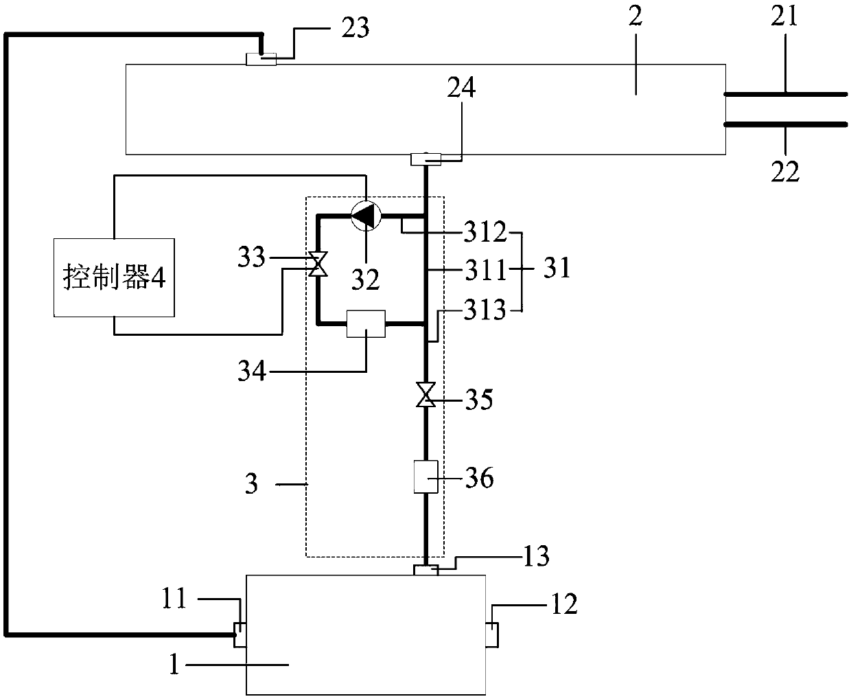
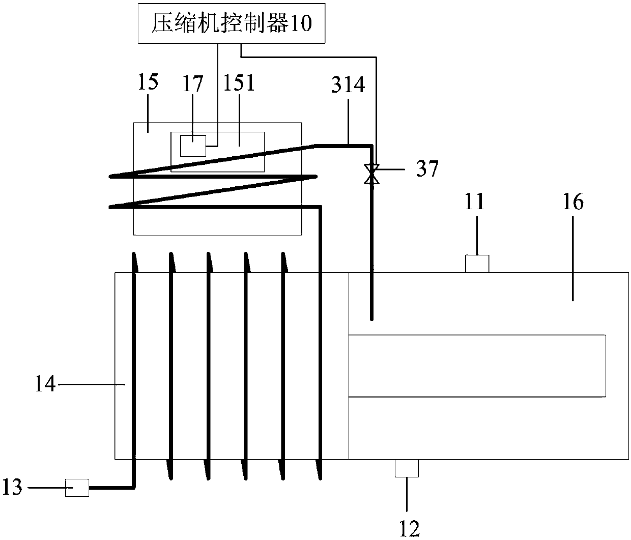
The invention relates to the technical field of air conditioners, in particular to an air conditioner. The air conditioner aims to solve the problem that an existing air conditioner is caused by insufficient liquid supply of a compressor. For the purpose, the air conditioner comprises a cooling pipeline system arranged between a cooling inlet and a condenser of the compressor, and partial refrigerant in the condenser flows to the cooling inlet of the compressor through the cooling pipeline system and then flows into the compressor; and the cooling pipeline system comprises a cooling pipeline and a pump device arranged on the cooling pipeline, the pump device is connected with a controller, and the controller is configured to control starting and stopping of the pump device according to thepressure ratio of the compressor. The pump device is started to ensure that the refrigerant in the condenser can flow into the compressor when the pressure ratio is lower than a set threshold value,so that the pressure ratio of the compressor is improved, the effect that the air conditioner can still normally run when the external temperature of the condenser is low is achieved, and thus it is ensured that the air conditioner can still meet the refrigeration requirements under the condition.

Description

technical field [0001] The invention relates to the technical field of air conditioners, in particular to an air conditioner. Background technique [0002] The compressor is one of the most important devices of the air conditioner. The compressor can compress the low-pressure gas refrigerant into a high-pressure gas refrigerant. Maintaining a certain pressure ratio of the compressor is very important for the normal operation of the air conditioner. Taking the magnetic levitation air conditioner as an example, the part of the liquid refrigerant that is heat exchanged in the condenser is usually returned to the compressor to cool the electronic components and motors inside the compressor. When the ambient temperature of the condenser is low, due to the problem of pressure difference, the refrigerant after heat exchange in the condenser cannot flow back into the compressor, and the situation of "insufficient liquid supply" of the compressor will occur, resulting in the failure ...

Claims


Application Information

Patent Timeline
IPC IPC(8): F24F11/84F24F11/86F24F11/64
CPCF24F11/64F24F11/84F24F11/86
Inventor 王铁伟张捷孟庆超杜娟
Owner QINGDAO HAIER AIR CONDITIONING ELECTRONICS CO LTD
Learn More