Multi-beam laser scanner

A laser scanner and beam scanning technology, applied in the field of laser scanners

Pending Publication Date: 2019-04-02
HEXAGON TECH CENT GMBH
View PDF13 Cites 3 Cited by
  • Summary
  • Abstract
  • Description
  • Claims
  • Application Information

AI Technical Summary

Problems solved by technology

[0021] For example, in the case of a line scanner, the orientation of the projected line on the object may vary with the azimuth of the rotating deflecting mirror, or as another example, have a collection of beams diverging from a single origin (e.g. cone of the beam) and using only a single scan direction, e.g. defined by a rotating mirror, the spatial resolution of the system is limited by generating a high density of dots in the scan direction but a low density of dots in a direction perpendicular to the scan direction

Method used


Image

  • Multi-beam laser scanner
  • Multi-beam laser scanner
  • Multi-beam laser scanner

Examples


Embodiment Construction

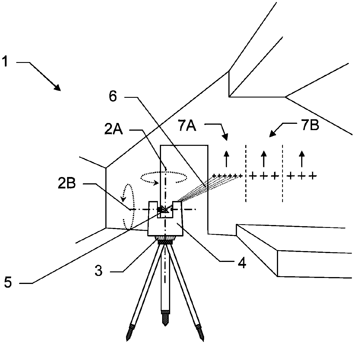
[0099] Figure 1a A typical laser scanner 1 in the field of building surveying is shown, which here has two axes of rotation 2A, 2B, the so-called slow (vertical) axis of rotation 2A (also called azimuth axis of rotation) and The so-called fast (horizontal) axis of rotation 2B. The laser scanner 1 includes a base 3 and a bracket 4 , wherein the bracket 4 is mounted on the base 3 in a manner to be rotatable around a slow axis 2A. The laser scanner also includes a rapidly rotating beam deflecting element 5 , which is mounted rotatably about a fast axis 2B in the holder 4 of the laser scanner 1 .

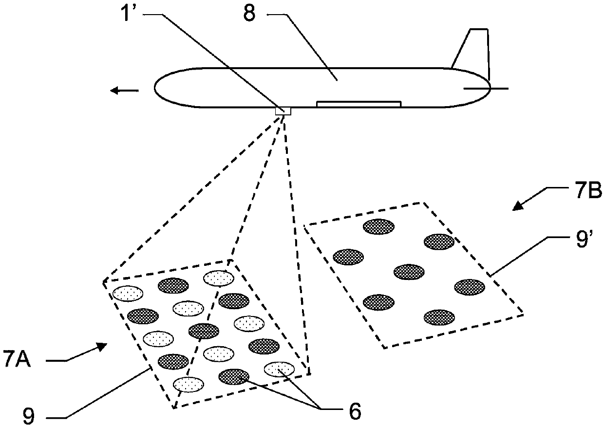
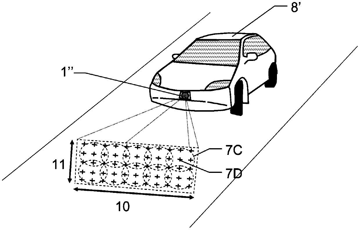
[0100] For example, for scanning linear or linearly drivable structures and environments, such as rail systems, roads, tunnel systems or airports, the base and thus the azimuth rotation axis 2A can be omitted. Instead, a laser scanner may be mounted on a transport device (eg, a ground or air support carrier vehicle). Such laser scanners with only one axis of beam rotation are often ...


PUM


Abstract

A multi-beam laser scanner is provided. The invention relates to a laser scanner (1,1',1") having multiple measuring beams (6) for optical surveying of an environment. According to the invention, thelaser scanner (1,1',1") is configured to provide scanning with at least two different multi-beam scan patterns (7A-D), wherein each multi-beam scan pattern (7A-D) is individually activatable by a computing unit (21) of the laser scanner (1,1',1").

Description

technical field [0001] The invention relates to a laser scanner for optical detection of an environment with simultaneously generated measuring beams. Background technique [0002] In order to detect objects or surfaces in the environment, methods of performing scanning by means of laser scanners are often used. In this case, the spatial position of the surface point is detected in each case by measuring the distance to the target surface point by the laser distance measuring beam and correlating this measurement with the angular information of the laser emission. From this distance and angle information, the spatial position of the detected point can be determined and eg the surface can be continuously measured. Usually, in parallel to this purely geometric detection of the surface, for example, an image recording by the camera takes place which contains, besides the overall view, for example, the surface texture, also other information. [0003] 3D scanning is a very eff...

Claims


Application Information

Patent Timeline
IPC IPC(8): G01S7/481G01B11/24G01S7/4865G01S17/26G01S17/89G01S17/931
CPCG01B11/2433G01S7/4817G01S17/42G01S17/89G01S7/4815G01S17/26G01S17/931G01C15/002G01S7/4808G01S7/4865G02B26/105
Inventor C·L·E·迪穆兰J·辛德林
Owner HEXAGON TECH CENT GMBH
Why Eureka
Try Eureka