Supercharge Your Innovation With Domain-Expert AI Agents!

Dual-communication antenna for roadside unit of electronic toll collection system road side unit

A technology of electronic non-stop and toll collection system, which is applied in the field of dual communication antennas and electronic non-stop toll collection system, can solve the problems such as the leakage of the rear car, and achieve the effect of narrow beam and high gain

Inactive Publication Date: 2019-04-02
南京誉凯电子科技有限公司
View PDF0 Cites 0 Cited by
  • Summary
  • Abstract
  • Description
  • Claims
  • Application Information

AI Technical Summary

Problems solved by technology

There are usually two cases of car-following interference: the first case is that the front and rear vehicles pass through the ETC lane one after another, and the RSU and the OBU of the rear car have a transaction. The vehicle behind the transaction is intercepted instead; the second situation is that when two vehicles pass by the ETC lane one after another, the vehicle in front has a transaction, but the vehicle following it also passes the ETC lane after the vehicle in front without a transaction , causing the rear car to miss buckle

Method used


Image

  • Dual-communication antenna for roadside unit of electronic toll collection system road side unit
  • Dual-communication antenna for roadside unit of electronic toll collection system road side unit
  • Dual-communication antenna for roadside unit of electronic toll collection system road side unit

Examples


Embodiment 1

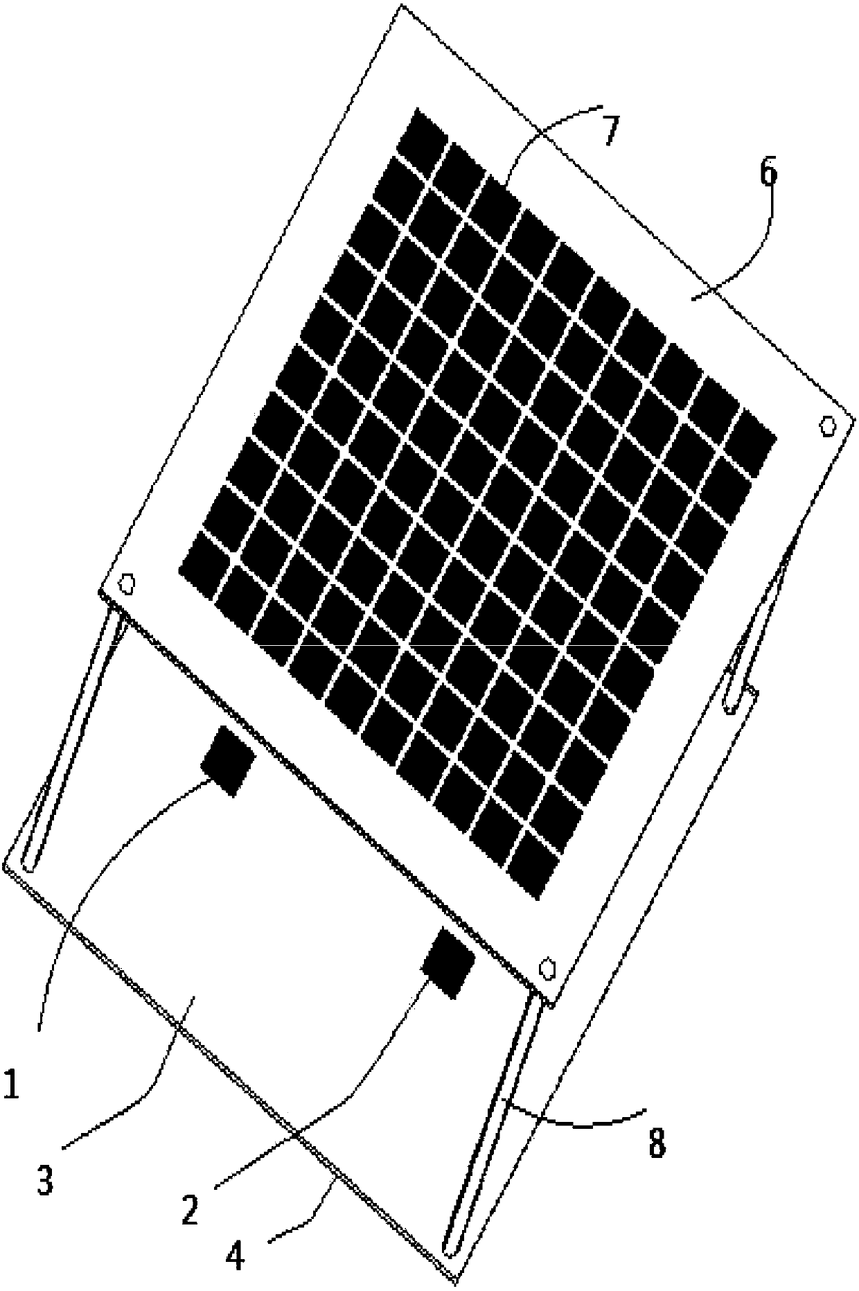
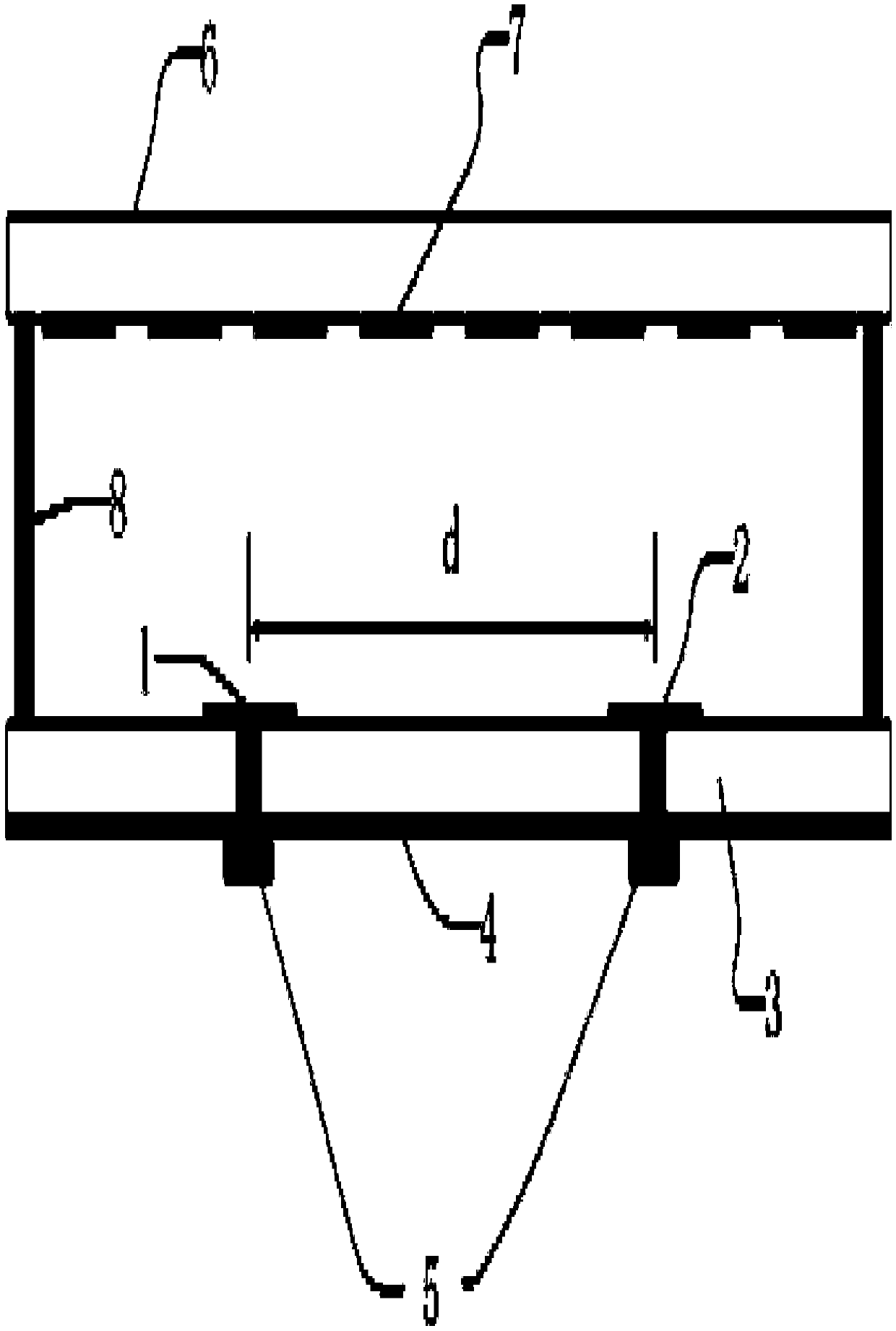
[0026] refer to figure 1 and figure 2 , the present invention includes: two metal patches 1 and 2, a dielectric substrate 3, a metal floor 4, a feed connector 5, an artificial electromagnetic medium coating 6 and a coating unit 7. in:

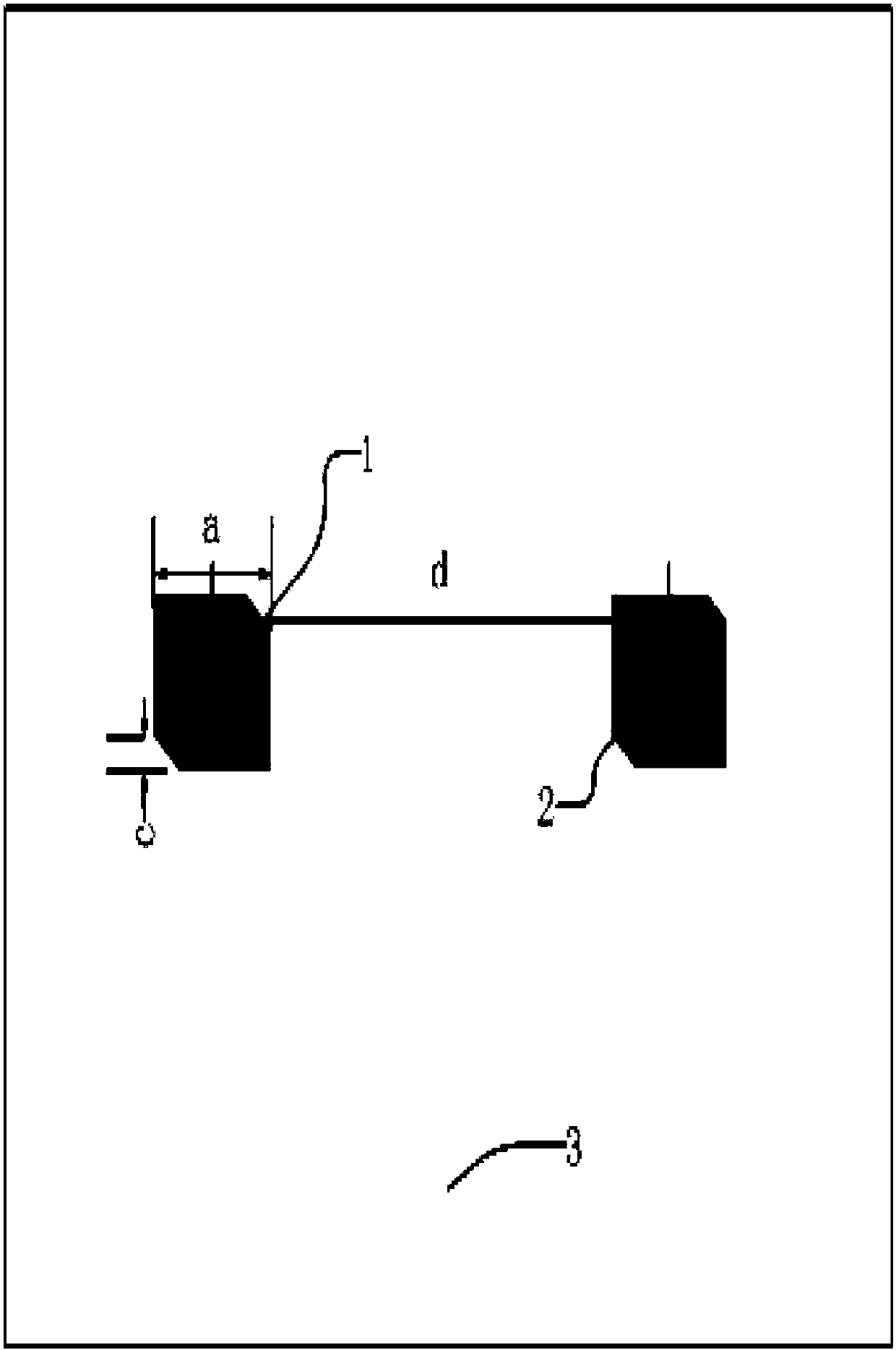
[0027] The metal patches 1 and 2 all adopt a square patch with a diagonal cut off, such as image 3 As shown, two separate degenerate modes are excited on the metal patch by cutting diagonally. When the antenna operating frequency is between the resonant frequencies of the two degenerate modes, adjust the size of the cut angle so that the two degenerate modes The modes are produced with a 90° phase difference, thereby achieving circular polarization. The cut corner in this embodiment is an isosceles right triangle, the side length a of the square patch is 14.7 mm, and the side length c of the cut corner of the isosceles right triangle is 2.3 mm. The metal patch 1 and the metal patch 2 are symmetrically etched on both sides of the center of...

Embodiment 2

[0035] refer to figure 2 , the present invention includes: two metal patches 1 and 2, a dielectric substrate 3, a metal floor 4, a feed connector 5, an artificial electromagnetic medium coating 6 and a coating unit 7. in:

[0036] The two metal patches 1 and 2 are rectangular patches, such as Figure 4 Shown, all the other structures are identical with embodiment 1. In the present embodiment, the length x of the two metal patches 1 and 2 is 14.9mm, and the width y is 14.5mm. The distance d between the metal patch 1 and the metal patch 2 is 80mm. The length b is 5.5 mm, the arrangement period t is 6 mm, the distance h between the upper surface of the dielectric substrate 3 and the lower surface of the artificial electromagnetic medium coating 6 is 22 mm, and other structural parameters are the same as those in Embodiment 1.

Embodiment 3

[0038] refer to figure 1 and figure 2 , the present invention includes: two metal patches 1 and 2, a dielectric substrate 3, a metal floor 4, a feed connector 5, an artificial electromagnetic medium coating 6 and a coating unit 7. The structural relationship between these components is the same as in Embodiment 1, but the parameters are different. In the present embodiment, the side length a of two metal patches 1 and 2 is 15mm, the side length c of the cut corner is 3mm, the distance d between the metal patch 1 and the metal patch 2 is 120mm, and the side of the cladding unit 7 The length b is 8 mm, the arrangement period t is 8.5 mm, the distance h between the upper surface of the dielectric substrate 3 and the lower surface of the artificial electromagnetic medium coating 6 is 22 mm, and other structural parameters are the same as those in Embodiment 1.


PUM


Abstract

The invention discloses a dual-communication antenna for an electronic toll collection system road side unit, which mainly solves the problem that a current electronic toll collection system is easy to generate car following interference. The antenna comprises two metal radiating patches (1 and 2), a dielectric substrate (3), a metal floor (4) and an artificial electromagnetic medium coating (6).Two metal patches (1 and 2) are symmetrically disposed on both sides of the center of the upper surface of the dielectric substrate (3), and are connected to a coaxial line through a 50[Omega] feed connector (5); the metal floor (4) is attached to the lower surface of the dielectric substrate (3); the artificial electromagnetic medium coating (6) is fixed at the upper portion of the dielectric substrate (3), and an FP cavity is formed between the artificial electromagnetic medium coating (6) and the dielectric substrate (3); the metal radiating patches (1 and 2) are subjected to feed to obtaintwo wave beams with different main lobe directions to control the near-far communication. The dual-communication antenna can achieve read-write control of different communication areas to avoid car following interference in the electronic toll collection system and ensure the normal toll collection of passing vehicles.

Description

technical field [0001] The invention belongs to the technical field of antennas, in particular to a dual communication antenna, which can be used in an electronic non-stop toll collection system of expressways. Background technique [0002] The electronic non-stop toll collection system ETC is one of the more advanced road and bridge toll collection methods in the world. The electronic non-stop charging system does not require parking, human operation, and cash transactions, which brings a lot of convenience to people and also plays a positive role in promoting the development of modern society. [0003] The ETC system achieves the automatic identification of the vehicle through the communication between the roadside unit RSU and the vehicle-mounted unit OBU installed on the vehicle windshield. In the case of no need to stop, it uses computer network technology to carry out settlement processing with the bank background to complete the process. Automatic deduction of toll...

Claims


Application Information

Patent Timeline
Patent Type & Authority Applications(China)
IPC IPC(8): H01Q1/38H01Q1/50H01Q3/24H01Q19/10H01Q1/22G07B15/06
CPCH01Q1/38G07B15/063H01Q1/2216H01Q1/50H01Q3/247H01Q19/104
Inventor 刘梅
Owner 南京誉凯电子科技有限公司
Features
  • R&D
  • Intellectual Property
  • Life Sciences
  • Materials
  • Tech Scout
  • Unparalleled Data Quality
  • Higher Quality Content
  • 60% Fewer Hallucinations
Learn More