Dual Communication Antennas for Electronic Toll Collection System
A technology of electronic non-stop charging system, which is applied in the field of dual communication antennas and electronic non-stop toll collection system, can solve the problem of missing car deduction and other problems, and achieve the effect of narrow beam and high gain
- Summary
- Abstract
- Description
- Claims
- Application Information
AI Technical Summary
Problems solved by technology
Method used
Image
Examples
Embodiment 1
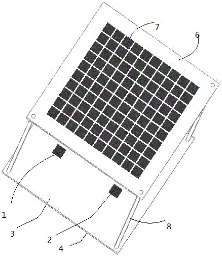
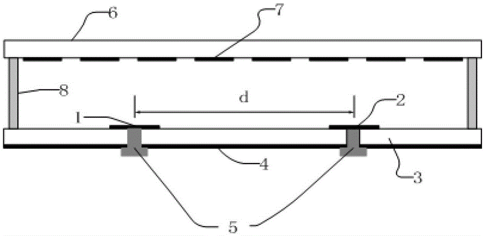
[0026] refer to figure 1 and figure 2 , the present invention includes: two metal patches 1 and 2, a dielectric substrate 3, a metal floor 4, a feed connector 5, an artificial electromagnetic medium coating 6 and a coating unit 7. in:
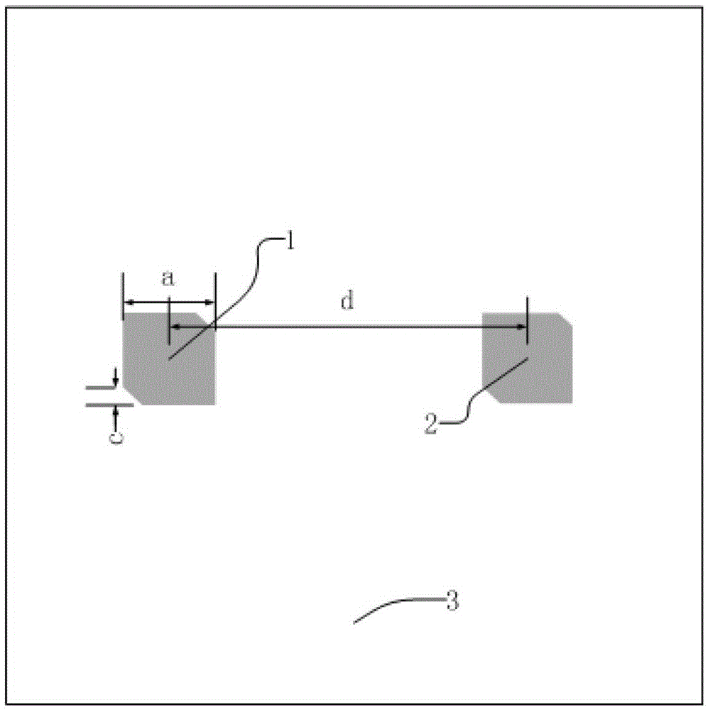
[0027] The metal patches 1 and 2 all adopt a square patch with a diagonal cut off, such as image 3 As shown, two separate degenerate modes are excited on the metal patch by cutting diagonally. When the antenna operating frequency is between the resonant frequencies of the two degenerate modes, adjust the size of the cut angle so that the two degenerate modes The modes are produced with a 90° phase difference, thereby achieving circular polarization. The cut corner in this embodiment is an isosceles right triangle, the side length a of the square patch is 14.7 mm, and the side length c of the cut corner of the isosceles right triangle is 2.3 mm. The metal patch 1 and the metal patch 2 are symmetrically etched on both sides of the center of...
Embodiment 2
[0035] refer to figure 2 , the present invention includes: two metal patches 1 and 2, a dielectric substrate 3, a metal floor 4, a feed connector 5, an artificial electromagnetic medium coating 6 and a coating unit 7. in:
[0036] The two metal patches 1 and 2 are rectangular patches, such as Figure 4 Shown, all the other structures are identical with embodiment 1. In the present embodiment, the length x of the two metal patches 1 and 2 is 14.9mm, and the width y is 14.5mm. The distance d between the metal patch 1 and the metal patch 2 is 80mm. The length b is 5.5 mm, the arrangement period t is 6 mm, the distance h between the upper surface of the dielectric substrate 3 and the lower surface of the artificial electromagnetic medium coating 6 is 22 mm, and other structural parameters are the same as those in Embodiment 1.
Embodiment 3
[0038] refer to figure 1 and figure 2 , the present invention includes: two metal patches 1 and 2, a dielectric substrate 3, a metal floor 4, a feed connector 5, an artificial electromagnetic medium coating 6 and a coating unit 7. The structural relationship between these components is the same as in Embodiment 1, but the parameters are different. In the present embodiment, the side length a of two metal patches 1 and 2 is 15mm, the side length c of the cut corner is 3mm, the distance d between the metal patch 1 and the metal patch 2 is 120mm, and the side of the cladding unit 7 The length b is 8 mm, the arrangement period t is 8.5 mm, the distance h between the upper surface of the dielectric substrate 3 and the lower surface of the artificial electromagnetic medium coating 6 is 22 mm, and other structural parameters are the same as those in Embodiment 1.
PUM
 Abstract
Description
Claims
Application Information
 - R&D
- Intellectual Property
- Life Sciences
- Materials
- Tech Scout
- Unparalleled Data Quality
- Higher Quality Content
- 60% Fewer Hallucinations
Browse by: Latest US Patents, China's latest patents, Technical Efficacy Thesaurus, Application Domain, Technology Topic, Popular Technical Reports.
© 2025 PatSnap. All rights reserved.Legal|Privacy policy|Modern Slavery Act Transparency Statement|Sitemap|About US| Contact US: help@patsnap.com


