System and method satellite television for receiving and switching satellite signals

A satellite signal and satellite TV technology, applied in the field of satellite TV, can solve the problem that the user terminal can only receive the same one, and achieve the effect of flexible use, easy modification, and small modification

Pending Publication Date: 2019-04-02
EARDA TECH CO LTD
View PDF0 Cites 1 Cited by
  • Summary
  • Abstract
  • Description
  • Claims
  • Application Information

AI Technical Summary

Problems solved by technology

[0004] To sum up, the current mobile satellite TV receiving system based on the ku band has the following defects: first, fixed TV equipment is required, and mobile smart terminals cannot be used to watch; second, each user can only watch the same program, and watch multiple programs Need to configure multiple set-top boxes
Third, the user can only control the antenna controller through the buttons, and cannot use the mobile smart terminal for remote control
Existing antenna controllers generally use the TS shunt chip to shunt the traffic. The principle is to configure its hardware channels according to user instructions to filter out the specified program information. Therefore, the existing antenna controller has only one output, which results in only one output for each user terminal. Can receive the same TV program

Method used


Image

  • System and method satellite television for receiving and switching satellite signals
  • System and method satellite television for receiving and switching satellite signals
  • System and method satellite television for receiving and switching satellite signals

Examples


Embodiment 1

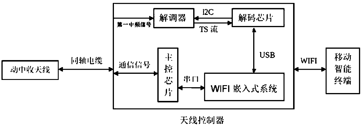
[0061] The functional block diagram of the satellite TV receiving and switching satellite signal system of Embodiment 1 is as follows figure 1 As shown in the figure, it consists of an antenna in motion, an antenna controller, and a mobile smart terminal. The receiving antenna in motion is connected to the antenna controller through a coaxial cable, and the antenna controller is connected to the mobile intelligent terminal through a WIFI network.

[0062] Antenna controller includes information display screen, control buttons, main control board, demodulator, decoding circuit and WIFI embedded module. The demodulator, decoding circuit (decoding chip), and WIFI embedded module are connected in sequence. The decoder receives the first intermediate frequency signal output by the antenna in motion, demodulates the signal, and converts the signal into a baseband signal. The decoding circuit converts the baseband signal Convert to TS stream signal, and output to WIFI embedded modul...


PUM


Abstract

The invention relates to a system and method of a satellite television for receiving and switching satellite signals. The TS shunting process of the method comprises the steps that a WIFI embedded module receives TS stream data, and transmits configuration information of all programs contained in the TS stream data at the current satellite frequency point to a requested mobile intelligent terminalaccording to a request; client state information of the mobile intelligent terminal is recorded when a program request initiated by the mobile intelligent terminal is received, wherein the client state information includes TCP connection information and program configuration information of a requested program; an analog transmission channel is created according to the program configuration information; and corresponding TS stream data packets are distributed according to the configuration of the analog transmission channel. The method replaces the filtering of the traditional TS shunting chipwith distribution, and can support different user terminals to watch different television programs. In addition, the TS shunting is achieved through the WIFI embedded module, the modification for theoriginal antenna controller is relatively small, the transformation is easy, and the implementation cost is low.

Description

technical field [0001] The invention relates to the technical field of satellite TV, in particular to a system and method for receiving and switching signals of satellite TV based on Ku band. Background technique [0002] At present, the mobile satellite TV receiving system based on the Ku-band includes a mobile antenna, an antenna controller, a satellite set-top box, and a TV main body, thus forming a complete receiving system to receive TV signals. The receiving antenna in motion needs to be connected with the antenna controller with a coaxial cable, and the set-top box needs to be connected with the signal ring outlet of the antenna controller with a coaxial cable, and finally output video and audio signals to the TV. [0003] figure 1 It is a schematic diagram of a traditional ku-band-based satellite TV receiving system in motion. The ship-mounted moving antenna is generally installed on the top of the ship, and the vehicle-mounted moving antenna is generally installed...

Claims


Application Information

Patent Timeline
Patent Type & Authority Applications(China)
IPC IPC(8): H04N21/41H04N21/426H04N21/4363H04N21/438H04N21/4385H04N21/61H04N7/20
CPCH04N7/20H04N21/41H04N21/4126H04N21/426H04N21/43637H04N21/4382H04N21/4385H04N21/6143
Inventor 单晓明区启康耿健李锦灵李小华
Owner EARDA TECH CO LTD
Why Eureka
Try Eureka