Physical channel sending method, receiving method, terminal equipment and network equipment

A physical channel and terminal equipment technology, which is applied in transmission path sub-channel allocation, wireless communication, signaling allocation, etc., can solve problems such as inability to meet low-latency services, and achieve the effect of reducing the waste of wireless resources

Active Publication Date: 2021-05-07
HUAWEI TECH CO LTD
View PDF2 Cites 0 Cited by
  • Summary
  • Abstract
  • Description
  • Claims
  • Application Information

AI Technical Summary

Problems solved by technology

Therefore, in the existing longterm evolution (LTE for short) system, the transmission time interval (transmission time interval, TTI for short) transmission mechanism based on one subframe can no longer meet the requirements of low-latency services.

Method used


Image

  • Physical channel sending method, receiving method, terminal equipment and network equipment
  • Physical channel sending method, receiving method, terminal equipment and network equipment
  • Physical channel sending method, receiving method, terminal equipment and network equipment

Examples


Embodiment Construction

[0048] Embodiments of the present invention can be applied to various communication systems, such as LTE systems, or other wireless communication systems using various wireless access technologies, such as code division multiple access, frequency division multiple access, time division multiple access, orthogonal frequency Systems with access technologies such as division multiple access and single carrier frequency division multiple access, and subsequent evolution systems, such as the fifth-generation 5G system.

[0049] The embodiments of the present invention can be applied to a wireless communication system including network equipment and terminal equipment (terminal device or terminal equipment). Specifically, the embodiments of the present invention may be applied to data transmission between a terminal device and a network device, data transmission between a terminal device and a terminal device, or data transmission between a network device and a network device. A ter...


PUM


Abstract

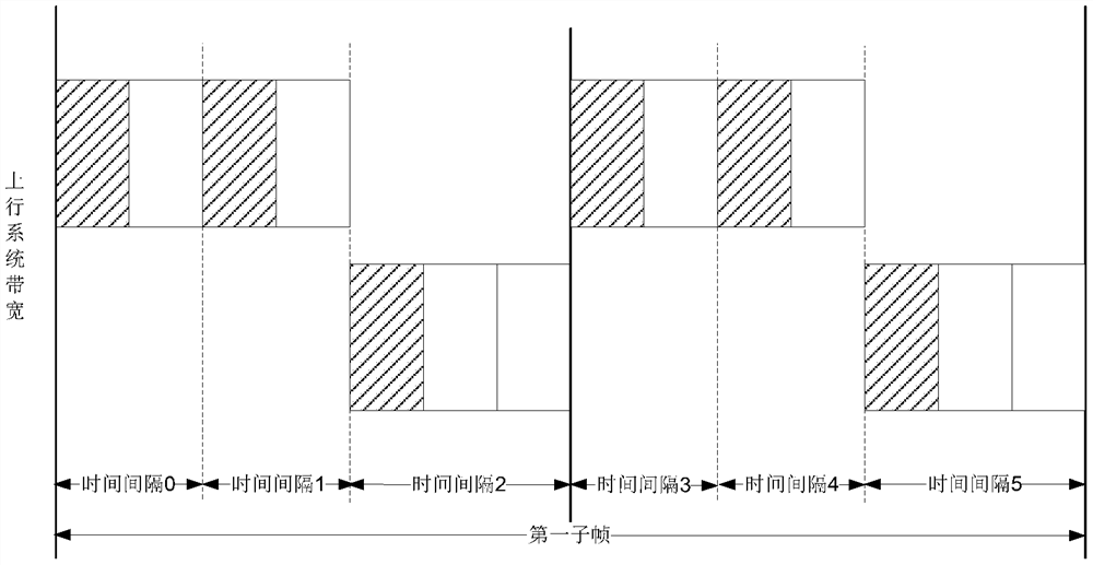
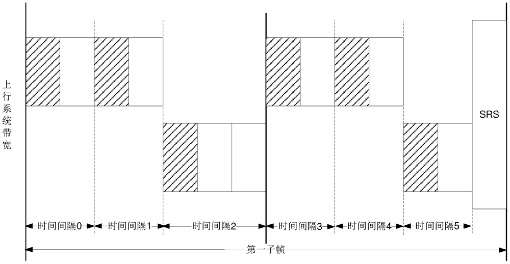
This application provides a physical channel sending method, receiving method, terminal equipment and network equipment. The physical channel sending method includes: a terminal device generates a physical channel, the physical channel is composed of N physical channel units, and N is a positive integer; the terminal device sends the physical channel in a first time domain resource; Wherein, the first time domain resource includes M time intervals, the N physical channel units are located on N time intervals in the M time intervals, and M is a positive integer greater than or equal to N. By adopting the method and wireless communication device provided in this application, wireless resources can be effectively multiplexed, thereby reducing the waste of wireless resources.

Description

technical field [0001] The present application relates to the field of wireless communication, in particular to a physical channel sending method, a receiving method, terminal equipment and network equipment. Background technique [0002] In a wireless communication system, latency is one of the important factors affecting user experience. New services that continue to emerge, such as services related to the Internet of Vehicles, also put forward higher and higher requirements for latency. Therefore, in the existing long term evolution (longterm evolution, LTE for short) system, a transmission mechanism based on a transmission time interval (transmission time interval, TTI for short) of one subframe cannot meet the requirements of low-latency services. In order to reduce the delay, the TTI length of the physical downlink shared channel (PDSCH for short), the physical uplink shared channel (PUSCH for short) and the physical uplink control channel (PUCCH for short) needs to b...

Claims


Application Information

Patent Timeline
Patent Type & Authority Patents(China)
IPC IPC(8): H04L1/00
CPCH04L1/00H04L5/22H04L5/003H04L5/0053H04L5/0094H04W72/12H04L5/001H04W72/0446H04W72/1263
Inventor 李超君邵家枫
Owner HUAWEI TECH CO LTD
Why Eureka
Try Eureka