
Head cooling device for emergency nursing

A cooling device and head technology, applied in the field of medical equipment, can solve the problem of ice blocks blocking the drain, and achieve the effects of cooling the head, ensuring safe use, and convenient storage

Inactive Publication Date: 2019-04-05
PEOPLES HOSPITAL OF DEYANG CITY
View PDF9 Cites 5 Cited by
  • Summary
  • Abstract
  • Description
  • Claims
  • Application Information

AI Technical Summary

Problems solved by technology

[0003] The currently published Chinese patent authorization announcement number is CN206612872U, a head cooling device for emergency care. Although it can cool the patient's head, ice cubes are inside the device. During the drainage process, ice cubes often block the drainage. mouth phenomenon occurs

Method used


Image

  • Head cooling device for emergency nursing
  • Head cooling device for emergency nursing
  • Head cooling device for emergency nursing

Examples


Embodiment 1

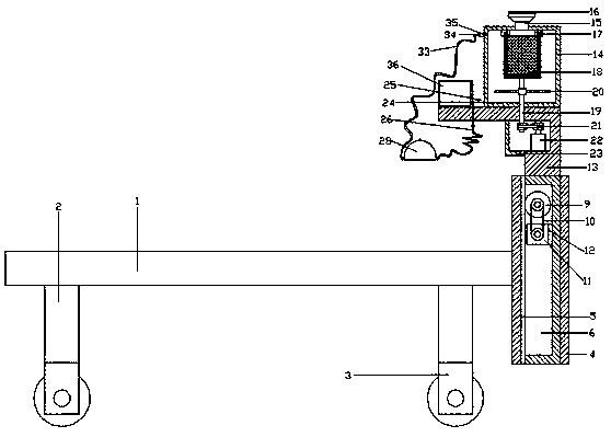
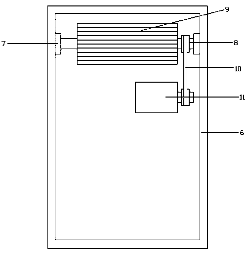
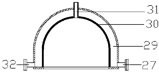
[0024] refer to Figure 1~3 , in the embodiment of the present invention, a head cooling device for emergency care, including a bed board 1, the four corners of the lower side of the bed board 1 are welded with supporting legs 2, and the lower side of the supporting legs 2 is equipped with rollers 3, which can effectively facilitate the operation of the equipment. Moving, the right side of the bed board 1 is fixedly equipped with a connecting frame 4, a rack 5 is installed on the left side wall of the connecting frame 4, and a connecting cover 6 is arranged on the right side of the rack 5, and the front and rear ends of the upper side of the connecting cover 6 pass through the bearing seat 7 is connected with the connecting shaft 8, the connecting shaft 8 is equipped with a gear 9, the gear 9 meshes with the rack 5, and the connecting shaft 8 on the front side of the gear 9 is connected with the first motor 11 through the first belt 10, the second The right side of a motor 11 ...

Embodiment 2

[0029] The difference from Embodiment 1 is that the upper middle part of the storage chamber 14 is provided with a feeding port 15, which can facilitate adding ice cubes to the inside of the storage chamber 14, so that the aqueous solution inside the storage chamber 14 is kept at zero temperature, and the upper side of the feeding port 15 is equipped with The sealing cover 16 can ensure the sealing of the equipment.


PUM


Abstract

The invention relates to the field of medical instruments and specifically relates to a head cooling device for emergency nursing. The head cooling device comprises a bed plate; a connecting frame isfixedly arranged on the right side of the bed plate; a rack is arranged on a left side wall of the connecting frame; a connecting cover is arranged on the right side of the rack; a support plate is fixedly connected with the upper side of the connecting cover; a storage chamber is fixedly connected with the upper side of the support plate; an annular limiting slot is fixedly formed on the top endin the storage chamber; an ice block storage net drum is arranged on the lower side of the annular limiting slot; a first connecting pipe is arranged on the lower end on the left side of the storage chamber; a first connecting hose is arranged on the lower side of the first connecting pipe; a water feeding pipe is connected with the first connecting hose; a helmet is arranged on the water feedingpipe; a chamber is formed in the helmet; a water draining pipe is arranged on the left side of the helmet; the water draining pipe is connected with a second connecting hose; the second connecting hose is connected with a second connecting pipe; a water pump is arranged on the second connecting pipe. The head cooling device for emergency nursing can be used for effectively and conveniently performing cooling treatment on the head of patient, and the head cooling device is convenient for use.

Description

technical field [0001] The invention relates to the field of medical equipment, in particular to a head cooling device for emergency care. Background technique [0002] Medical devices refer to instruments, equipment, utensils, in vitro diagnostic reagents and calibrators, materials, and other similar or related items that are directly or indirectly used on the human body, including required computer software; their effects are mainly obtained through physical means, not Obtained by pharmacological, immunological or metabolic means, or with the participation of these means but only as an auxiliary function; its purpose is the diagnosis, prevention, monitoring, treatment or alleviation of disease; the diagnosis, monitoring, treatment, alleviation or function of injury Compensation; examination, replacement, regulation or support of physiological structures or processes; life support or maintenance; pregnancy control; providing information for medical or diagnostic purposes by...

Claims


Application Information

Patent Timeline
Patent Type & Authority Applications(China)
IPC IPC(8): A61F7/00A61G13/00A61G13/10
CPCA61F7/00A61F2007/0002A61F2007/0056A61G13/009A61G13/104A61G2210/70
Inventor 黎文娟
Owner PEOPLES HOSPITAL OF DEYANG CITY
Learn More