
Continuous automatic blanking and punching composite die and stamping process

A blanking punching and compound die technology, applied in the direction of punching tools, manufacturing tools, metal processing equipment, etc., can solve problems such as affecting production efficiency, poor trimming quality, and poor pressing effect.

Inactive Publication Date: 2019-04-05
ANHUI JIANGHUAI AUTOMOBILE GRP CORP LTD
View PDF6 Cites 1 Cited by
  • Summary
  • Abstract
  • Description
  • Claims
  • Application Information

AI Technical Summary

Problems solved by technology

[0002] At present, the processing technology for truck beams and other components mainly adopts compression molding, and some powerful or large-volume manufacturers mostly use blanking and punching composite molds for one-time punching and molding, but the existing technology design Blanking and punching composite molds mostly use manual loading and unloading, use the upper mold unloading plate to press the material by its own weight, and use the existing rigid punching rod of the machine tool to return the material
But relying on the self-weight of the upper die to press the material, not only the pressing effect is not good, but the trimming quality is poor, resulting in poor product quality consistency, and there is also the disadvantage of high noise. At the same time, relying on the self-weight of the upper die base to press the material, resulting in a long return time during the stamping process , affecting production efficiency

Method used


Image

  • Continuous automatic blanking and punching composite die and stamping process
  • Continuous automatic blanking and punching composite die and stamping process
  • Continuous automatic blanking and punching composite die and stamping process

Examples


Embodiment Construction

[0030] Embodiments of the present invention are described in detail below, and examples of the embodiments are shown in the drawings, wherein the same or similar reference numerals denote the same or similar elements or elements having the same or similar functions throughout. The embodiments described below by referring to the figures are exemplary only for explaining the present invention and should not be construed as limiting the present invention.

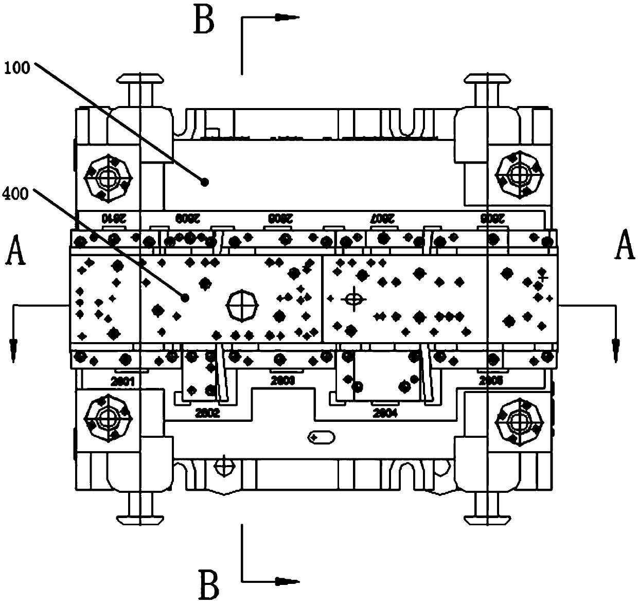
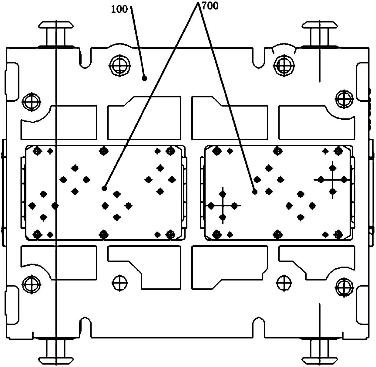
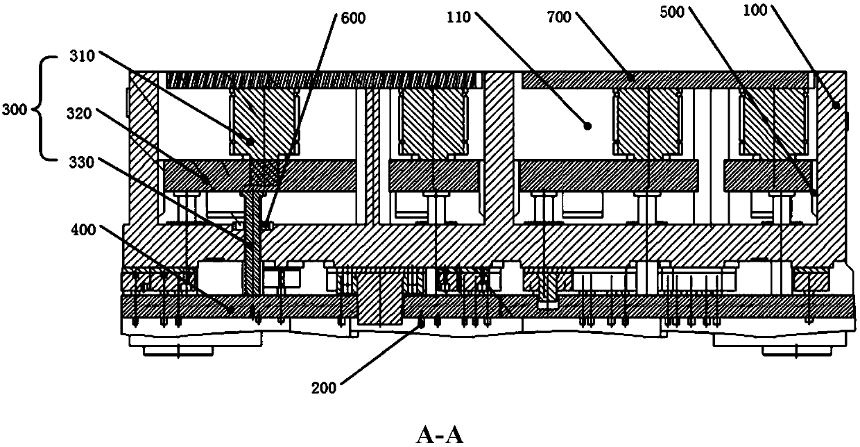
[0031] Such as Figure 1 to Figure 4 As shown, the continuous automatic blanking and punching composite mold provided by the embodiment of the present invention includes an upper mold base 100, a lower mold base and a guide column. die, the upper die base 100 drives the punch 200 to move along the guide column to match the die, and the continuous automatic blanking and punching compound die also includes a plurality of pressing mechanisms 300 and pressing plates 400. Wherein, each pressing mechanism 300 includes a driving par...


PUM


Abstract

The invention discloses a continuous automatic blanking and punching composite die and a stamping process. The continuous automatic blanking and punching composite die comprises a plurality of material pressing mechanisms and material pressing plates, each material pressing mechanism comprises a driving part, a force transmission plate and a plurality of force transmission rods; and the material pressing plates are fixed to driving ends of the driving parts through the force transmission plates and the force transmission rods. When the device is in the using process, an upper die base drives amale die to move downwards to be in contact with the upper surface of a blank in a lower die base, firstly, the driving ends of the driving parts drive the material pressing plates to carry out material pressing through the force transmission plates and the force transmission rods, then, the male die further descends to finish stamping, then the male die moves upwards to complete the stripping, then the driving parts release the material pressing, and the stamping process is completed. In the process, in the stamping and stripping process of the male die, the independent material pressing plates are arranged for material pressing, so that the problems that in the prior art, the material pressing is not stable and the quality of the stamped products is not consistent due to the fact that only the upper die base depending on self weight is used for pressing materials can be solved, the noise can be reduced, and the production efficiency is improved.

Description

technical field [0001] The invention relates to the technical field of automobile molds, in particular to a continuous automatic blanking and punching composite mold and a stamping process. Background technique [0002] At present, the processing technology for truck beams and other components mainly adopts compression molding, and some powerful or large-volume manufacturers mostly use blanking and punching composite molds for one-time punching and molding, but the existing technology design Blanking and punching composite molds mostly use manual loading and unloading, use the upper mold unloading plate to press the material by its own weight, and use the existing rigid punching rod of the machine tool to return the material. But relying on the self-weight of the upper die to press the material, not only the pressing effect is not good, but the trimming quality is poor, resulting in poor product quality consistency, and there is also the disadvantage of high noise. At the sa...

Claims


Application Information

Patent Timeline
IPC IPC(8): B21D28/14B21D28/34B21D43/00
CPCB21D28/14B21D28/34B21D43/003
Inventor 汤敏汤茁禹夏咪咪崔礼春徐迎强刘迪祥杜长胜
Owner ANHUI JIANGHUAI AUTOMOBILE GRP CORP LTD
Learn More