The Method of Improving the Welding Quality of Pigtail Laser
A laser welding, laser technology, applied in the direction of welding equipment, welding equipment, auxiliary welding equipment, etc., can solve the problems of laser transmitter and wire alignment position deviation, mis-collision coupling fixture, coupling fixture movement, etc., to improve welding quality, the effect of avoiding movement of the coupling fixture
- Summary
- Abstract
- Description
- Claims
- Application Information
AI Technical Summary
Problems solved by technology
Method used
Image
Examples
Embodiment 1
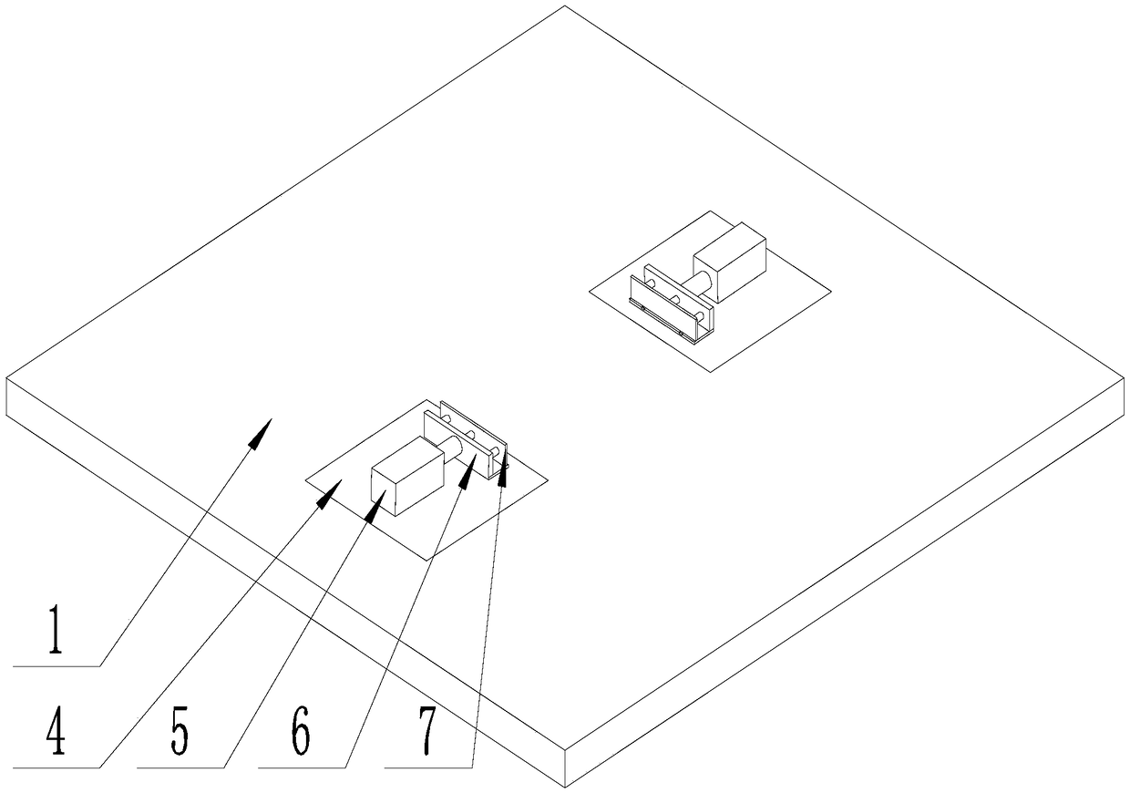
[0046] Such as Figure 1-Figure 9 As shown, the present invention improves the method for pigtail laser welding quality, comprises the steps:
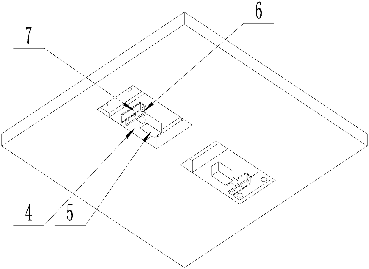
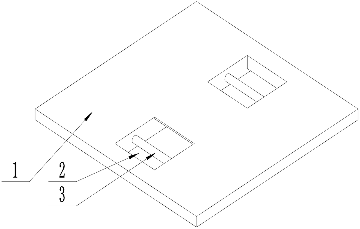
[0047] Step A Preparation: place the coupling fixture on the workbench 1 and between the through holes 2, then turn over the mounting plate 4 so that the telescopic assembly is located on the upper surface of the workbench 1;
[0048] Step B fixation: start the telescopic assembly until the telescopic end of the telescopic assembly touches the base of the coupling fixture, and fix the coupling fixture between the telescopic assemblies;
[0049] Step C installation: Install the laser transmitter and optical fiber integrated assembly on the coupling fixture;
[0050] Step C welding: adjust the coupling fixture to maximize the power of the laser transmitter through the optical fiber, and then perform welding;
[0051] Step D dismantling: remove the welded pigtail laser from the coupling fixture, and then install the next laser transmitt...
Embodiment 2
[0054] The present invention is based on embodiment 1, and the present invention is further described.
[0055] Such as Figure 1-Figure 9 As shown, in the method for improving the welding quality of the pigtail laser in the present invention, there are two through holes 2, both of which are located on the workbench 1, and their axes are all perpendicular to the upper surface of the workbench 1, and the mounting plate 4 and telescopic There are two components, and each is located in a through hole, and the telescopic components are respectively connected to a mounting plate 4;
[0056] Each through hole 2 is provided with a rotating shaft 3, the axis of the rotating shaft 3 is perpendicular to the axis of the corresponding through hole 2, and one end of the rotating shaft 3 is connected to the hole wall on one side of the through hole 2, and the axis of the rotating shaft 3 The other end moves through the mounting plate 4 and is connected to the hole wall on the other side of...
Embodiment 3
[0058] The present invention is based on embodiment 2, and the present invention is further described.
[0059] Such as Figure 1-Figure 9 As shown, the method for improving the welding quality of pigtail laser in the present invention, the telescopic assembly includes a pneumatic cylinder 5 and a push plate 6 connected in sequence, the end of the piston rod of the pneumatic cylinder 5 is connected with the push plate 6, and the push plate 6 It is perpendicular to the axis of the pneumatic cylinder 5; when the telescopic assemblies are located on the upper surface of the workbench 1, the push plates 6 of the telescopic assemblies are opposite to each other.
[0060] An elastic rubber plate 7 is provided on the end of the push plate 6 away from the pneumatic cylinder 5 , and the elastic rubber plate 7 is connected to the push plate 6 through magnets.
[0061] The arrangement of the elastic rubber plate 7 is to protect the surface of the base of the coupling fixture close to th...
PUM
 Abstract
Description
Claims
Application Information
 - R&D
- Intellectual Property
- Life Sciences
- Materials
- Tech Scout
- Unparalleled Data Quality
- Higher Quality Content
- 60% Fewer Hallucinations
Browse by: Latest US Patents, China's latest patents, Technical Efficacy Thesaurus, Application Domain, Technology Topic, Popular Technical Reports.
© 2025 PatSnap. All rights reserved.Legal|Privacy policy|Modern Slavery Act Transparency Statement|Sitemap|About US| Contact US: help@patsnap.com


