
Angle-changeable air cylinder side hole machining fixing tool

A technology for fixing tooling and side holes, used in positioning devices, metal processing equipment, metal processing machinery parts, etc., can solve the problems of poor positioning accuracy due to angle changes, slow manual clamping speed, poor adjustability, etc., to ensure dimensional accuracy. and geometric tolerances, saving re-installation time, and improving work efficiency

Pending Publication Date: 2019-04-05
马鞍山市德善金属成型科技有限公司
View PDF0 Cites 2 Cited by
  • Summary
  • Abstract
  • Description
  • Claims
  • Application Information

AI Technical Summary

Problems solved by technology

[0002] In the compressor cylinder plus production and processing industry, the machine tool is a workpiece clamping tool and a tool power head, so only one part can be clamped and processed at a time. After the processing is completed, the next workpiece can be processed after disassembly, and so on. , slow efficiency, unable to adapt to automated production
[0003] When doing side hole processing, ordinary fixed tooling is manually clamped, and most of the manual clamping is fixed by tightening the bolts and pressing blocks. During the fixing process, the operator’s grasp of the force cannot be completely unified, and the force of tightening the bolts is large. Indentation will be left when the bolt is tightened, and the fixation will be unstable when the bolt is tightened, and the workpiece will easily deviate, causing serious consequences; and the manual clamping speed is slow and the productivity is low. When ordinary tooling is clamped, it often has a single position and involves Poor positioning accuracy and poor adjustability for angular changes, especially in mass production, it is difficult to control the size tolerance and shape tolerance of the side hole. Therefore, a clamping tool that can solve the above problems is urgently needed

Method used


Image

  • Angle-changeable air cylinder side hole machining fixing tool
  • Angle-changeable air cylinder side hole machining fixing tool
  • Angle-changeable air cylinder side hole machining fixing tool

Examples


Embodiment Construction

[0029] The following will clearly and completely describe the technical solutions in the embodiments of the present invention with reference to the accompanying drawings in the embodiments of the present invention. Obviously, the described embodiments are only some, not all, embodiments of the present invention. Based on the embodiments of the present invention, all other embodiments obtained by persons of ordinary skill in the art without making creative efforts belong to the protection scope of the present invention.

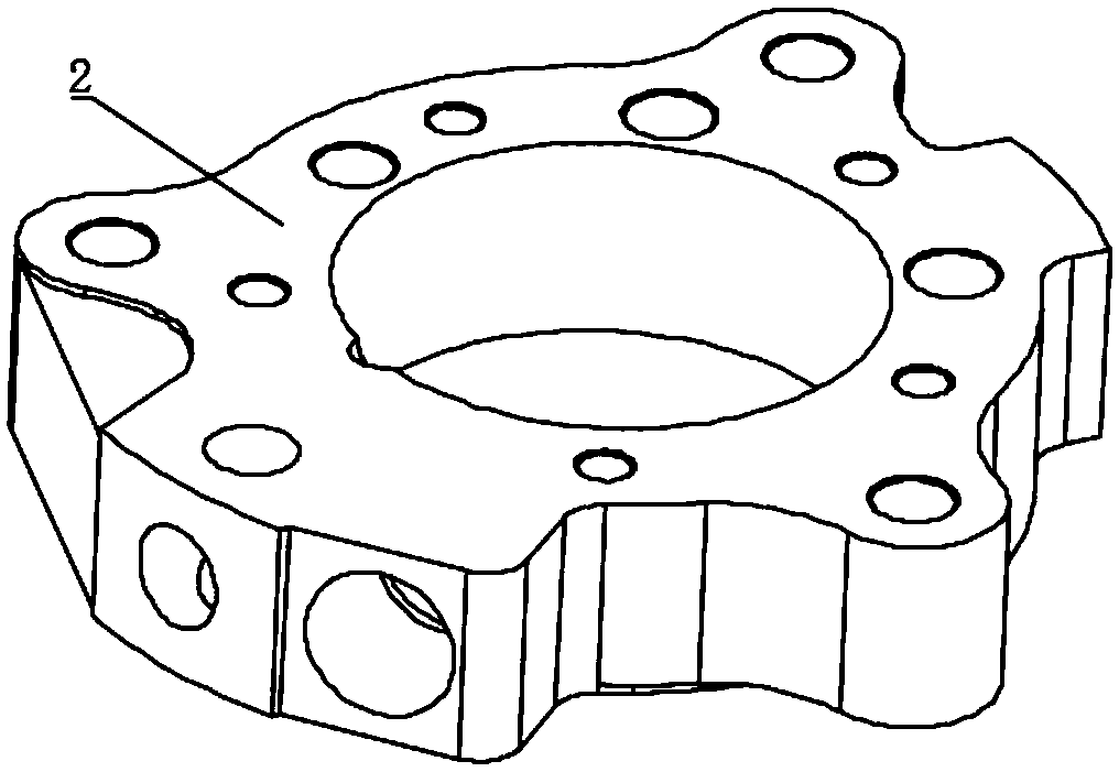
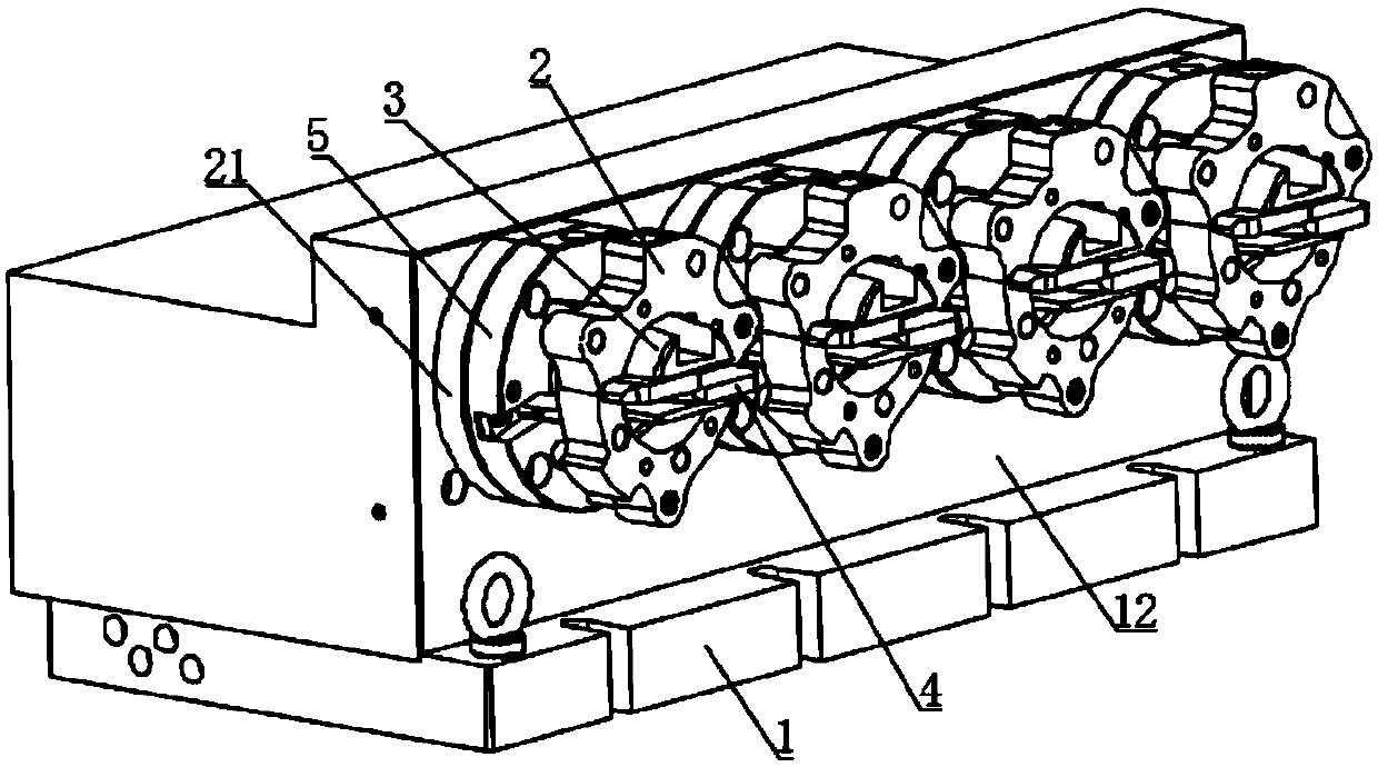
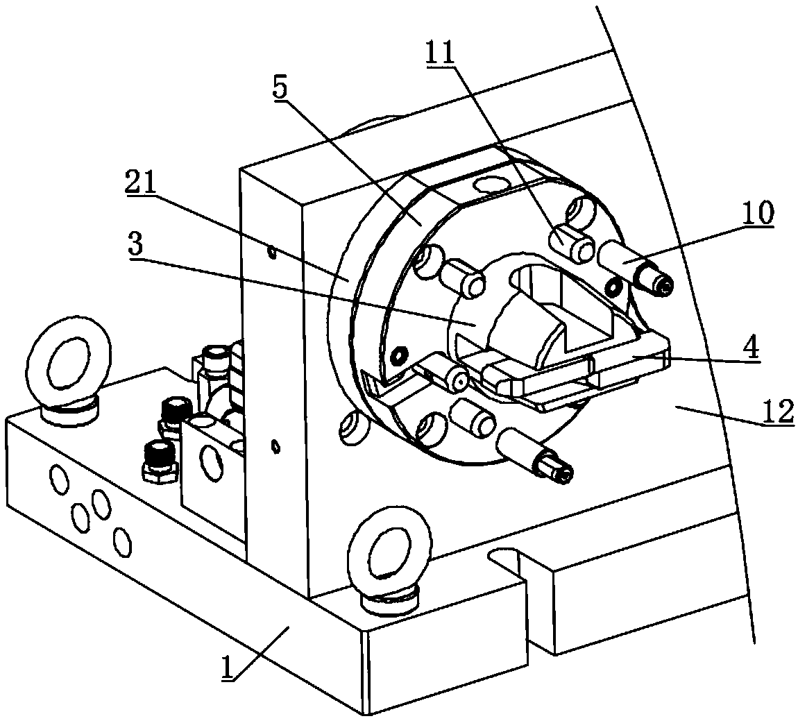
[0030] The present invention is a fixed tool for machining the side hole of the cylinder, which can be equipped with single station and multi-station. In this embodiment, the multi-station is described in detail:

[0031] like Figure 2-Figure 8 As shown, a cylinder side hole can be angled to process a fixed tool, including a base 1, a main body support block 12 installed on the base 1, and a plurality of stations installed on the main body support block 12 fo...


PUM


Abstract

The invention discloses an angle-changeable air cylinder side hole machining fixing tool. The angle-changeable air cylinder side hole machining fixing tool comprises a base and a station installed onthe base. The station comprises a mounting seat which is transversely connected to the interior of a main body supporting block in an inserting mode. A cavity with an opening in the front side is formed in the mounting base. An oil cylinder piston capable of sliding is arranged in the cavity. Two overlapped vertical frames are rotationally mounted on the oil cylinder piston and comprise two long edges and two short edges perpendicular to the long edges. The long edges are connected with a piston oil cylinder. The two short edges extend to the outside of the mounting base, extend in opposite directions, are used for pressing a workpiece, and penetrate through an opening groove. The angle-changeable air cylinder side hole machining fixing tool is moderate in clamping force and firm in fixingand does not damage the workpiece easily. Positioning plates can be replaced on the same tool to be compatible with a plurality of products with different models. Feeding and discharging can be conveniently carried out. The labor is saved. The productivity of an enterprise is improved.

Description

technical field [0001] The invention belongs to the technical field of fixed tooling, and in particular relates to a fixed tooling for machining a side hole of a cylinder at an angle. Background technique [0002] In the compressor cylinder plus production and processing industry, the machine tool is a workpiece clamping tool and a tool power head, so only one part can be clamped and processed at a time. After the processing is completed, the next workpiece can be processed after disassembly, and so on. , slow efficiency, unable to adapt to automated production. [0003] When doing side hole processing, ordinary fixed tooling is manually clamped, and most of the manual clamping is fixed by tightening the bolts and pressing blocks. During the fixing process, the operator’s grasp of the force cannot be completely unified, and the force of tightening the bolts is large. Indentation will be left when the bolt is tightened, and the fixation will be unstable when the bolt is tigh...

Claims


Application Information

Patent Timeline
Patent Type & Authority Applications(China)
IPC IPC(8): B23Q3/08B23Q3/18
CPCB23Q3/08B23Q3/082B23Q3/18
Inventor 雒应学李雪林周爱民
Owner 马鞍山市德善金属成型科技有限公司
Learn More