Overlapping and assembling station for panel light assembling line

A lighting and wiring technology, applied in the direction of manufacturing tools, workpiece clamping devices, workshop equipment, etc., can solve the problems of uneven assembly quality, low yield rate, uncontrollable quality, etc., to improve the line drawing speed, The effect of fast execution, improvement of assembly efficiency and assembly quality

Pending Publication Date: 2019-04-05
KUNSHAN TUOYU AUTOMATION TECH CO LTD
View PDF0 Cites 4 Cited by
  • Summary
  • Abstract
  • Description
  • Claims
  • Application Information

AI Technical Summary

Problems solved by technology

[0003] The most commonly used flat panel lamp in LED lamps, its optical components include light guide plate and diffuser plate lamp, etc. In the prior art, because the assembly of these optical components is relatively simple, it is only necessary to put each optical component into the lamp frame in order. Therefore, many of them are assembled manually, which leads to uneven assembly quality and low yield rate. Among them, the diffusion plate is the outermost layer of the panel light (the layer visible to the user in the finished panel light). Optical materials, and the diffusion plate is used to interfere with the light to increase the angle of illumination. However, since the diffusion plate is located on the outermost layer, its side will also produce light guide effect and cause light leakage. For this light leakage, the simplest The commonly used method is to coat the side with a black marker pen to cover it before assembly. In the prior art, the work of drawing lines and coating is also done manually, which is slow and the quality is uncontrollable.

Method used


Image

  • Overlapping and assembling station for panel light assembling line
  • Overlapping and assembling station for panel light assembling line
  • Overlapping and assembling station for panel light assembling line

Examples


Embodiment

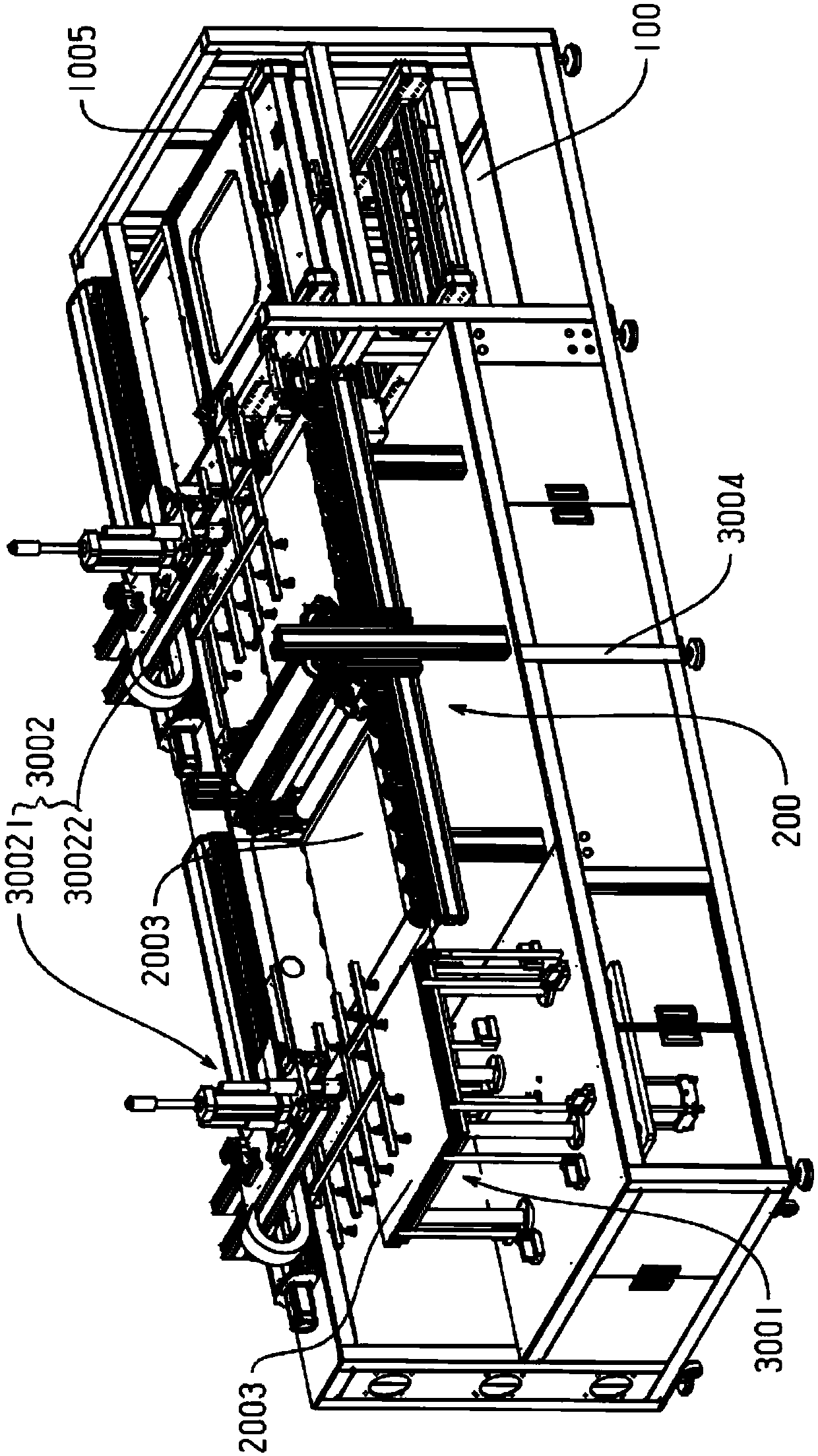
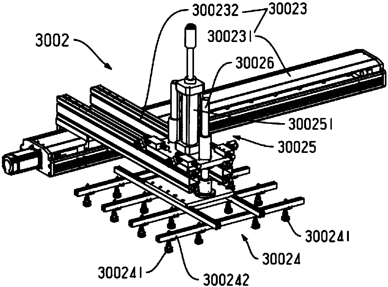
[0040] Embodiment: a stacking station for a panel lamp assembly line, such as figure 1 As shown: it includes a stacking frame 3004 and a feeding device 3001 connected to the stacking frame, a line drawing device 200 and a transmission line body 100, between the feeding device and the line drawing device and the line drawing device A grabbing device 3002 is provided between the transmission line body and the grabbing device includes a first grabbing device 30021 and a second grabbing device 30022 with the same structure, and the workpiece 2003 to be assembled passes through the first grabbing device 30022. The device grabs and places it on the line-drawing device. After the line-drawing device completes the line-drawing action for the workpiece, the second grabbing device grabs and places the workpiece on the light frame 1005 of the panel lamp. The light frame is installed on the transmission line body;

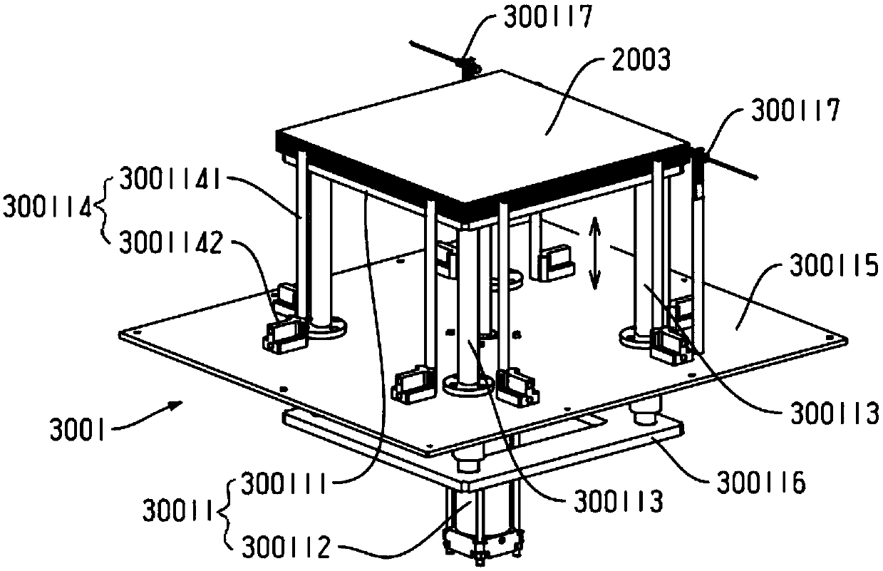
[0041] The feeding device includes an elevating bin 30011, and several w...


PUM


Abstract

The invention discloses an overlapping and assembling station for a panel light assembling line. The overlapping and assembling station for the panel light assembling line comprises an overlapping rack, a feeding device, a line drawing device and a transmission line body, wherein the feeding device, the line drawing device and the transmission line body are connected to the overlapping rack; gripping devices are arranged between the feeding device and the line drawing device as well as the line drawing device and the transmission line body, and comprise a first gripping device and a second gripping device with the same structures; a workpiece to be assembled is gripped through the first gripping device and placed on the line drawing device; and after the line drawing device draws a line for the workpiece, the second gripping device grips the workpiece and places the workpiece to a light frame of a panel light; and the light frame is located on the transmission line body. According to the overlapping and assembling station for the panel light assembling line provided by the invention, automatic feeding is accomplished through the gripping devices, automatic line drawing is accomplished through the line drawing device, and finally automatic overlapping and assembling are accomplished through the gripping devices, so that the assembling efficiency and the assembling quality are improved.

Description

technical field [0001] The invention belongs to the technical field of automation equipment, and in particular relates to an assembly equipment of a flat panel lamp. Background technique [0002] Since the official commercialization of LED lights in 1960, they have been used only as indicator light sources for instruments and meters at first, to traffic signal lights, high-position brake lights, display screens, mobile phones, and lantern decorations, and now in urban lighting engineering lighting. It has been widely used, showing a good development space and a broad market prospect; [0003] The most commonly used flat panel lamp in LED lamps, its optical components include light guide plate and diffuser plate lamp, etc. In the prior art, because the assembly of these optical components is relatively simple, it is only necessary to put each optical component into the lamp frame in order. Therefore, many of them are assembled manually, which leads to uneven assembly quality...

Claims


Application Information

Patent Timeline
IPC IPC(8): B25B27/00B25H7/04B25B11/02
CPCB25B11/02B25B27/00B25H7/04
Inventor 吴涛
Owner KUNSHAN TUOYU AUTOMATION TECH CO LTD
Why Eureka
Try Eureka