Paper grid drawing device
A technology for drawing grids and paper, applied in instruments, writing utensils, printing, etc., can solve complex, difficult, and difficult to adjust grids and other problems, and achieve easy hanging, simple operation, fast grids and adjustable grids effect of size
- Summary
- Abstract
- Description
- Claims
- Application Information
AI Technical Summary
Problems solved by technology
Method used
Image
Examples
Embodiment 1
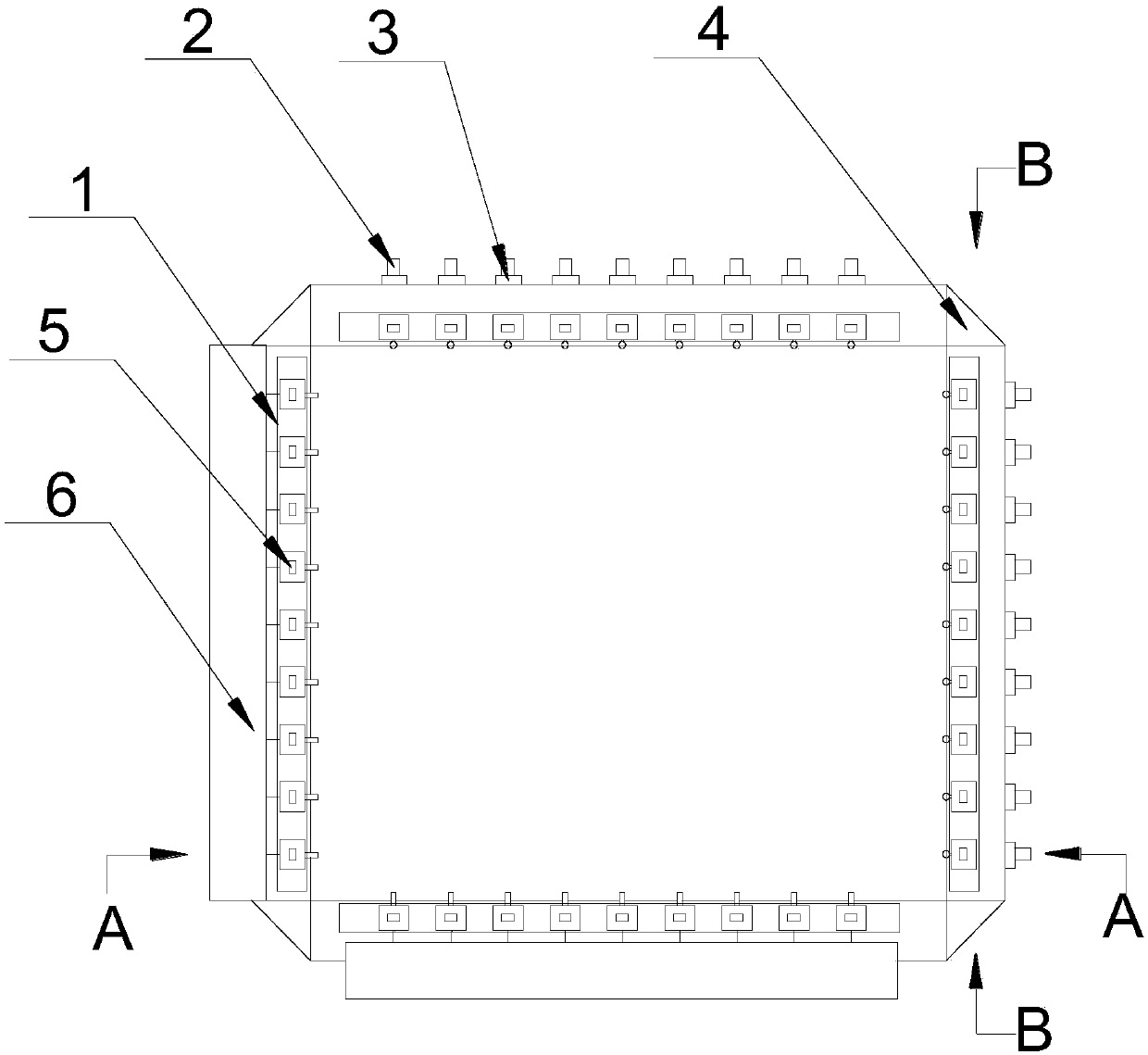
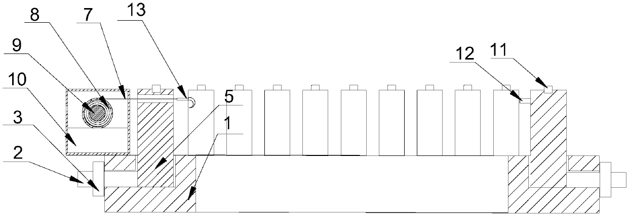
[0033] see Figure 1~5 , a paper framer, comprising a frame assembly, the frame assembly is provided with a scale, the frame assembly includes four bars 1 and connected in turn to form a square, the top surface of the bar frame 1 is provided with multiple bars along its long side A set of positioning columns 5, the positioning columns 5 can slide along the long side of the bar frame 1, and the bar frame 1 is provided with a limit mechanism that can be used to limit the movement of the positioning column 5, and a group of adjacent bar frames 1 in the frame assembly are provided with Dyeing box 6, a rotating shaft assembly is arranged in the dyeing box 6, and the rotating shaft assembly is sequentially wound with a plurality of groups of crimping lines 7 corresponding to adjacent positioning columns 5 one by one along the long side direction of the bar frame 1, and the crimping lines 7 One end passes through the dyeing box 6 and the corresponding positioning column 5 in sequence...
Embodiment 2
[0037] see Figure 1~5 , a paper framer, comprising a frame assembly, the frame assembly is provided with a scale, the frame assembly includes four bars 1 and connected in turn to form a square, the top surface of the bar frame 1 is provided with multiple bars along its long side A set of positioning columns 5, the positioning columns 5 can slide along the long side of the bar frame 1, and the bar frame 1 is provided with a limit mechanism that can be used to limit the movement of the positioning column 5, and a group of adjacent bar frames 1 in the frame assembly are provided with Dyeing box 6, a rotating shaft assembly is arranged in the dyeing box 6, and the rotating shaft assembly is sequentially wound with a plurality of groups of crimping lines 7 corresponding to adjacent positioning columns 5 one by one along the long side direction of the bar frame 1, and the crimping lines 7 One end passes through the dyeing box 6 and the corresponding positioning column 5 in sequence...
Embodiment 3
[0043] see Figure 1~5 , a paper framer, comprising a frame assembly, the frame assembly is provided with a scale, the frame assembly includes four bars 1 and connected in turn to form a square, the top surface of the bar frame 1 is provided with multiple bars along its long side A set of positioning columns 5, the positioning columns 5 can slide along the long side of the bar frame 1, and the bar frame 1 is provided with a limit mechanism that can be used to limit the movement of the positioning column 5, and a group of adjacent bar frames 1 in the frame assembly are provided with Dyeing box 6, a rotating shaft assembly is arranged in the dyeing box 6, and the rotating shaft assembly is sequentially wound with a plurality of groups of crimping lines 7 corresponding to adjacent positioning columns 5 one by one along the long side direction of the bar frame 1, and the crimping lines 7 One end passes through the dyeing box 6 and the corresponding positioning column 5 in sequence...
PUM
 Abstract
Description
Claims
Application Information
 - R&D
- Intellectual Property
- Life Sciences
- Materials
- Tech Scout
- Unparalleled Data Quality
- Higher Quality Content
- 60% Fewer Hallucinations
Browse by: Latest US Patents, China's latest patents, Technical Efficacy Thesaurus, Application Domain, Technology Topic, Popular Technical Reports.
© 2025 PatSnap. All rights reserved.Legal|Privacy policy|Modern Slavery Act Transparency Statement|Sitemap|About US| Contact US: help@patsnap.com


