Rail transit traction brake fusion control system and method applying the same

A technology that integrates control and rail transit. It is applied to electric braking systems, motor vehicles, electric vehicles, etc. It can solve problems such as affecting the accurate execution of braking commands, increasing system complexity, and increasing data transmission delays, reducing coupling. , the effect of avoiding data transmission and improving reliability

Active Publication Date: 2019-04-05
ZHUZHOU CSR TIMES ELECTRIC CO LTD
View PDF5 Cites 16 Cited by
  • Summary
  • Abstract
  • Description
  • Claims
  • Application Information

AI Technical Summary

Problems solved by technology

Since the traction and braking control are divided into two control modules, when the braking command is executed through electric-air hybrid braking, the traction control module needs to receive the electric braking force control command sent by the braking control module, and control the traction actuator to perform electric braking. Manual operation, that is, data interaction between the brake control module and the traction control module is req...

Method used


Image

  • Rail transit traction brake fusion control system and method applying the same
  • Rail transit traction brake fusion control system and method applying the same
  • Rail transit traction brake fusion control system and method applying the same

Examples


Embodiment 1

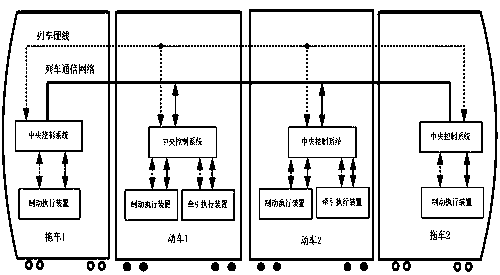
[0053] Such as Figure 4 and 5 As shown, the present embodiment provides a rail transit traction braking fusion control system, including a central control system of a trailer and a pulling fusion control system of a bullet train; the central control system includes a central controller 6; the pulling fusion control system includes A traction fusion controller 1 integrating a traction control module and a braking control module, and a braking actuator 2 and a traction actuator 3 respectively connected to the traction fusion controller 1; 4 Receive the traction and braking commands sent by the central controller 6 or receive the traction and braking level commands sent by the controller from the train hard line 5, and then respectively control the actuators to perform traction and braking operations.

[0054] The working principle of this embodiment is as follows:

[0055] The central control system of the trailer with the driver controller, as the main control unit of the wh...

Embodiment 2

[0062] Such as Figure 6 As shown, the difference between this embodiment and Embodiment 1 is that the brake actuator 2 includes a bogie brake actuator; the traction actuator 3 includes a bogie traction actuator.

[0063] In this embodiment, the rack control mode is used to perform traction and braking operations.

[0064]The central controller 6 distributes the total force required for traction and braking to the diversion fusion controller 1 of each train according to the number of bogies through logical judgment and calculation, and the central controller 6 sends the braking command or braking level The command is sent to each pinning fusion controller 1, and the pinning fusion controller 1 sends the required air braking force to the bogie 1 brake actuator 21 of the brake actuator 2 and the bogie 2 brake actuator through the air brake control command Mechanism 22, and the brake actuator 21 of bogie 1 and the brake actuator 22 of bogie 2 respectively control the basic brake...

Embodiment 3

[0067] Such as Figure 7 As shown, the difference between this embodiment and Embodiment 1 is that the brake actuator 2 includes a brake actuator controller 20 and a bogie brake actuator; the traction actuator 3 includes a traction actuator controller 30 and Bogie traction actuator.

[0068] In this embodiment, the vehicle control mode is used to perform traction and braking operations.

[0069] According to logical judgment and calculation, the central controller 6 distributes the total force required for traction and braking to each train according to the number of trains through braking instructions or braking level instructions, and the fusion controller 1 receives the central controller 6 The brake instruction or brake level instruction sent sends the air brake control instruction to the brake execution controller 20 of the brake actuator 2, and the brake actuator controller 20 controls the brake actuator 21 and the brake actuator 21 of the bogie 1. The foundation brake...


PUM


Abstract

The invention relates to the technical field of rail transit trains, and specifically relates to a rail transit traction brake fusion control system and a method applying the same. The system includescentral control systems of trailers and traction brake fusion control systems of bullet trains; the central control systems include central controllers; the traction brake fusion control systems include traction brake fusion controllers integrated with traction control modules and brake control modules, and brake executing devices and traction executing devices which are respectively connected tothe traction brake fusion controllers; and the traction brake fusion controllers receive traction or brake instructions sent by the central controllers through a train communication network or receive the traction or brake instructions sent by master controllers from a train hard wire, and respectively control the executing devices to execute traction and brake operation. As a control system canbe integrated through the individual traction control module and brake control module, data transmission between modules can be avoided, and the reliability and accuracy of the system can be enhanced.

Description

technical field [0001] The invention relates to the technical field of rail transit trains, in particular to a rail transit traction braking fusion control system and method. Background technique [0002] The rail transit central control system distributes the traction control system, brake control system, auxiliary power supply system, air conditioning control system, door control system, passenger information system, event recording unit, man-machine interface unit and train automatic driving system through the train communication network. All intelligent units in the whole train are connected into a train network. The train central control system exchanges information with the connected subsystems through the train communication network. [0003] Such as figure 1 As shown, the traditional traction control system and the braking control system have independent controllers. In order to ensure that the brake shoe wear is minimized and the braking response is accelerated du...

Claims


Application Information

Patent Timeline
IPC IPC(8): B61C17/00B61L15/00B60L7/24
CPCB60L7/24B60L2200/26B61C17/00B61L15/0036Y02T90/16
Inventor 余接任钱华夏帅应振华梁鹏廖云何红成刘增华阳彬武
Owner ZHUZHOU CSR TIMES ELECTRIC CO LTD
Why Eureka
Try Eureka