Technique for cooling a combustion engine

An internal combustion engine, cooling liquid technology, applied in the control of coolant flow, liquid cooling, engine cooling, etc., can solve the problems of increasing the heat sink, increasing the installation space, insufficient use, etc.

Active Publication Date: 2019-04-05
MAN NUTZFAHRZEUGE AG
View PDF4 Cites 0 Cited by
  • Summary
  • Abstract
  • Description
  • Claims
  • Application Information

AI Technical Summary

Problems solved by technology

On the one hand, increasing the heat sink will increase the rotating mass of the viscous clutch and increase the required installation space
On the other hand, this air cooling is just not sufficient, since the coolant pump is switched on at high engine loads, whereby the viscous clutch arranged behind the radiator is subjected to the same increased temperature of the cooling air

Method used


Image

  • Technique for cooling a combustion engine
  • Technique for cooling a combustion engine
  • Technique for cooling a combustion engine

Examples


Embodiment Construction

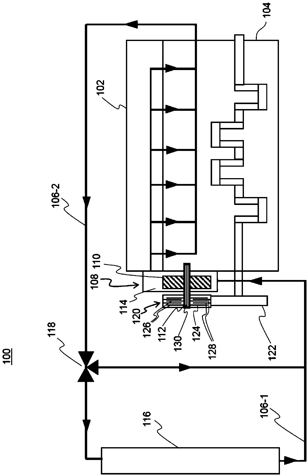
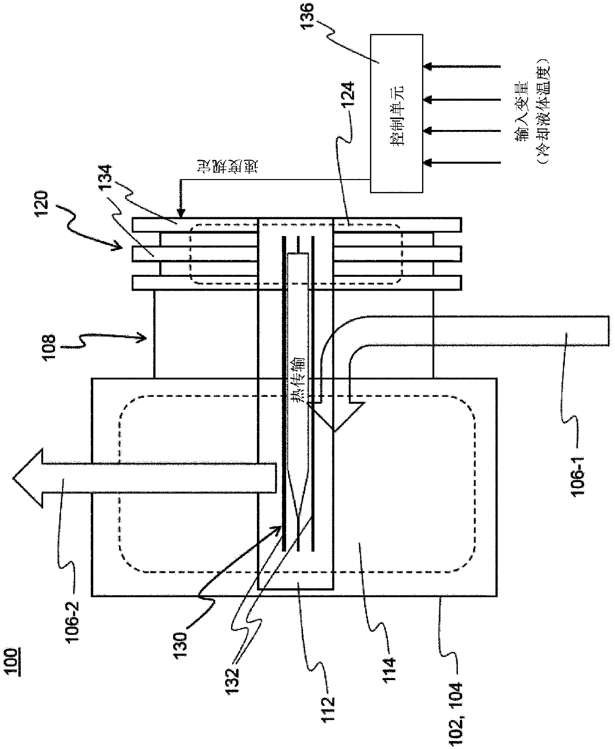
[0028] figure 1 A first embodiment of the internal combustion engine is shown generally designated by the reference numeral 100 . The internal combustion engine 100 includes a cylinder head 102 and an engine block 104 , which are connected to a cooling liquid circuit, generally designated with reference numeral 106 . Internal combustion engine 100 also includes a coolant pump 108 , which is connected on the inlet side to input 106 - 1 of coolant circuit 106 . Cooling liquid pump 108 is in fluid connection on the outlet side with cooling lines in cylinder head 102 and engine block 104 .

[0029] The cooling liquid pump 108 includes a rotating wheel 110 (such as an impeller or propeller) on a drive shaft 112 in a pump housing. The running wheel 110 and the pump-side end of the drive shaft 112 are immersed in the cooling liquid 114 of the cooling liquid circuit 106 , which fills the pump housing. The cooling liquid 114 comprises, for example, water with additives for raising t...


PUM


Abstract

An internal combustion engine 100 is disclosed and includes: a cooling liquid circuit (106-1, 106-2) , which is connected to a cylinder head 102 and an engine block 104 of the internal combustion engine and which includes a cooling liquid pump 108. The cooling liquid pump 108 includes a drive shaft 112 and is capable of conveying cooling liquid in the cooling liquid circuit (106-1, 106-2). Further, the internal combustion engine 100 includes a Visco clutch 120. The Visco clutch 120 is arranged for the drive 122 by the internal combustion engine 100. The Visco clutch 120 includes a clutch fluid124 for torque transmission. At the output side, the Visco clutch is connected to the drive shaft 112 of the cooling liquid pump 108. The drive shaft 112 of the cooling liquid pump 108 include at least one heat pipe 130. The heat pipe 130 is in heat exchange with the clutch fluid 124 as a heat source and the cooling liquid 114 as a heat sink.

Description

technical field [0001] The invention relates to an internal combustion engine, for example for driving a motor vehicle. In particular, a technique for cooling a viscous clutch (silicon oil clutch) of an internal combustion engine is introduced. Background technique [0002] Automobiles, in particular commercial vehicles, use viscous clutches for controllably driving a coolant pump of a coolant circuit of an internal combustion engine. The coolant pump of a truck (LKW), which is rigidly coupled to the internal combustion engine, has an average power consumption of, for example, 7 kW. The full power of the cooling liquid pump (for example in the case of horizontal driving routes and high speeds) is generally not necessary for sufficient heat removal with the cooling liquid of the internal combustion engine. Fuel savings of, for example, 0.5%-1.5% can be achieved by the on-demand control of the cooling liquid pump. An example of such a conventional control of a cooling liqui...

Claims


Application Information

Patent Timeline
Patent Type & Authority Applications(China)
IPC IPC(8): F01P3/22F01P5/12F01P7/16F02B67/04F04D15/00F16D35/00F28D15/04F28D15/02F04D13/02
CPCF01P3/22F01P5/12F01P7/162F02B67/04F04D13/021F04D15/00F16D35/00F28D15/02F28D15/04F01P2003/2278F01P7/164F16D35/005F16D2300/021F01P3/02F01P3/20F16D2300/0214F01P2003/024F01P2003/021F16D35/022
Inventor 亚历山大·斯驰亚罗罗伯特·玛顿斯
Owner MAN NUTZFAHRZEUGE AG
Why Eureka
Try Eureka