Infrared temperature image generating chip, device and method

An infrared temperature and image generation technology, applied in the direction of measuring devices, radiation pyrometry, instruments, etc., can solve the problems of distortion and clarity, and the difficulty of generating dynamic infrared temperature images, so as to reduce optical loss, ensure resolution and Clarity, an effect that improves image brightness and clarity

Pending Publication Date: 2019-04-05
QUALPER OPTOELECTRONICS TECH SHANGHAI CO LTD
View PDF0 Cites 0 Cited by
  • Summary
  • Abstract
  • Description
  • Claims
  • Application Information

AI Technical Summary

Problems solved by technology

The generation of dynamic infrared temperature images is relatively

Method used


Image

  • Infrared temperature image generating chip, device and method
  • Infrared temperature image generating chip, device and method
  • Infrared temperature image generating chip, device and method

Examples


Embodiment Construction

[0045] In order to make the content of the present invention clearer and easier to understand, the content of the present invention will be further described below in conjunction with the accompanying drawings. Of course, the present invention is not limited to this specific embodiment, and general replacements known to those skilled in the art are also covered within the protection scope of the present invention.

[0046] The following is attached Figure 1-14 The present invention will be described in further detail with specific examples. It should be noted that the drawings are all in a very simplified form, using imprecise scales, and are only used to facilitate and clearly achieve the purpose of assisting in describing the present embodiment.

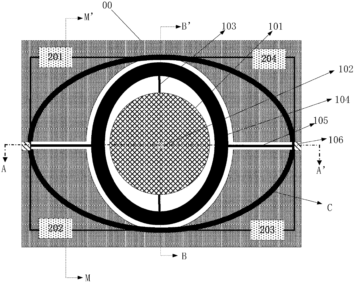
[0047] see figure 1 , the infrared temperature image generation chip 00 in this embodiment includes: an infrared light source, a MEMS image scanning unit, a computing unit 201 and a transmission interface. The MEMS image scanni...


PUM

PropertyMeasurementUnit
Thicknessaaaaaaaaaa

Abstract

The invention provides an infrared temperature image generating chip, device and method. An MEMS image scanning unit is used for acquiring image information data of an object; and a calculation unit is used for obtaining temperature image information data. An image acquisition unit is integrated on an MEMS scanning micromirror adopted by the image scanning unit, particularly, the image acquisitionunit is arranged on a reflector and can be used for receiving reflected light beams from the outside along with the swinging of the reflector along a torsion arm, and fast generation of a large number of pixels is realized by using the swinging of the MEMS scanning micromirror, so that the resolution and the definition of a dynamic infrared temperature image generated in a real-time transmissionprocess are ensured.

Description

technical field [0001] The invention relates to the technical field of image acquisition, in particular to an infrared temperature image generation chip, device and temperature image generation method. Background technique [0002] Existing various image acquisition devices generally use light source output and reflector reflection. On different optical paths of the reflector, image acquisition devices are used to acquire object reflected beam signals. Since the image acquisition device is separated from the mirror, the beam energy is consumed and the signal is distorted. Moreover, the resulting image acquisition device has a large volume, which is not conducive to miniaturization and thinning. [0003] With the improvement of people's living standards and the advancement of science and technology, various electronic devices tend to be miniaturized and thinned for easy portability. Moreover, the requirements for the quality of the acquired images are getting higher and hig...

Claims


Application Information

Patent Timeline
IPC IPC(8): G01J5/00G08C17/02
CPCG01J5/00G01J2005/0077G01J2005/0092G08C17/02
Inventor 汪际军
Owner QUALPER OPTOELECTRONICS TECH SHANGHAI CO LTD
Why Eureka
Try Eureka