Small tip-enhanced Raman spectrum measurement device and detection method thereof

A tip-enhanced Raman and spectral measurement technology, applied in the field of spectral measurement, can solve the problems of complex structure of Raman spectral measurement device, increased operation complexity, signal strength attenuation, etc., to reduce loss and construction complexity, and improve signal collection Efficiency, volume reduction effect

Pending Publication Date: 2021-06-25
XIAMEN UNIV
View PDF13 Cites 2 Cited by
  • Summary
  • Abstract
  • Description
  • Claims
  • Application Information

AI Technical Summary

Problems solved by technology

Although such a structure reduces the difficulty in designing the instrument, it also leads to the disadvantages of the entire needle-tip-enhanced Raman spectroscopy measurement device, such as complex structure, bulky size, and serious signal intensity attenuation; and the split design makes it possible to use different optical path modules. The control and data collection software not only greatly increases the complexity of the operation, but also lacks the coordinated control between various modules

Method used


Image

  • Small tip-enhanced Raman spectrum measurement device and detection method thereof
  • Small tip-enhanced Raman spectrum measurement device and detection method thereof
  • Small tip-enhanced Raman spectrum measurement device and detection method thereof

Examples


Embodiment 1

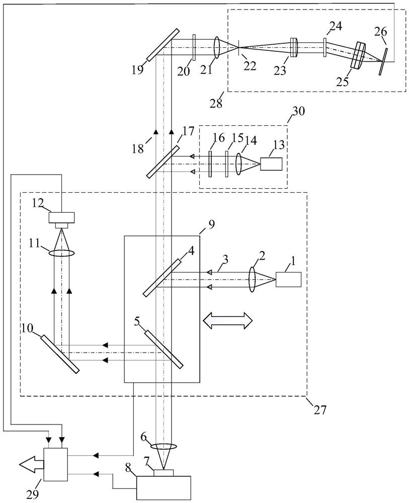
[0056] Such as figure 1 Shown, a kind of small-sized tip-enhanced Raman spectroscopy measuring device of the present invention, it comprises:

[0057] dichroic mirror 17;

[0058] The laser light source module 30 is arranged on the incident direction of the light path of the dichroic mirror 17, and is used to output laser light;

[0059] The objective lens 6 is arranged on the light path reflection direction of the dichroic mirror 17;

[0060] Three-dimensional translation stage 8, its carrying surface faces the end face of objective lens 6 away from dichroic mirror 17 and is used for placing the sample 7 to be measured;

[0061] The laser reflector 19 is arranged on the light path transmission direction of the dichroic mirror 17;

[0062] The spectral signal acquisition module 28 is arranged in the reflection direction of the optical path of the laser mirror 19, and is used to acquire the Raman signal light;

[0063] The laser focusing mirror 21 is arranged on the optical...

Embodiment 2

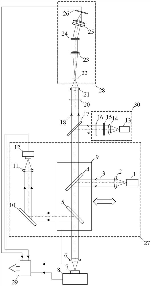
[0090] Such as image 3 As shown, this embodiment is roughly the same as Embodiment 1, and the difference is that in this embodiment, the laser reflector in Embodiment 1 is removed, and the specific structure of this embodiment is:

[0091] A small tip-enhanced Raman spectroscopy measurement device, which includes:

[0092] dichroic mirror 17;

[0093] The laser light source module 30 is arranged on the incident direction of the light path of the dichroic mirror 17, and is used to output laser light;

[0094] The objective lens 6 is arranged on the light path reflection direction of the dichroic mirror 17;

[0095]Three-dimensional translation stage 8, its carrying surface faces the end face of objective lens 6 away from dichroic mirror 17 and is used for placing the sample 7 to be measured;

[0096] Spectral signal acquisition module 28, arranged in the light path transmission direction of dichroic mirror 17, and used to acquire Raman signal light;

[0097] The laser focu...


PUM


Abstract

The present invention discloses a small tip-enhanced Raman spectrum measurement device and a detection method thereof. The device comprises a laser light source module, a dichroscope, an auxiliary calibration module, an objective lens and a three-dimensional translation stage which are sequentially arranged along a light path, and further comprises a long-pass optical filter, a laser focus lens and a spectral signal acquisition module which are sequentially arranged on the transmission side of the dichroscope, and a control and data processing module which is connected with the auxiliary calibration module, the three-dimensional translation platform and the spectral signal acquisition module. According to the scheme, a white light illumination and microscopic imaging light path, an excitation and collection light path and a Raman spectrum light path are organically integrated together, a sample, a needle tip and laser are accurately coupled by utilizing the white light illumination and microscopic imaging light path before measurement, the maximum excitation efficiency is realized, and the excitation and collection light path is directly coupled with the Raman spectrum light path, so that the loss of a peripheral light path in the measurement process is reduced, and the structure size of the whole measurement device is reduced while the spectral resolution capability is ensured by optimizing the light path structure of each part.

Description

technical field [0001] The invention relates to the technical field of spectrum measurement, in particular to a small needle-tip enhanced Raman spectrum measurement device and a detection method thereof. Background technique [0002] Raman spectroscopy technology is widely used in chemistry, polymer materials, geology, life sciences and other fields because of its advantages of easy operation and high sensitivity. Tip-enhanced Raman spectroscopy technology is the most promising technology for Raman spectroscopy technology. How to realize it at present? The miniaturization and integration of the needle-tip-enhanced Raman spectroscopy measurement device and the reduction of signal light loss are the key technologies to complete the small-scale integrated needle-tip-enhanced Raman spectroscopy measurement device. [0003] When traditional Raman spectroscopy is used for material research, due to the small Raman scattering cross-section and strong fluorescence interference, it is...

Claims


Application Information

Patent Timeline
Patent Type & Authority Applications(China)
IPC IPC(8): G01N21/65
CPCG01N21/658
Inventor 范贤光曾英杰支瑜亮王昕任斌
Owner XIAMEN UNIV
Why Eureka
Try Eureka