
Onboard three-optical-axis consistency test component, system and method

A technology for testing components and consistency, applied in the direction of determining the optical axis, testing optical performance, determining the position of the lens, etc., can solve problems affecting measurement accuracy, optical axis deviation, and large environmental impact, so as to improve detection accuracy and facilitate installation and adjustment , small size effect

Pending Publication Date: 2019-04-05
XI'AN INST OF OPTICS & FINE MECHANICS - CHINESE ACAD OF SCI
View PDF8 Cites 9 Cited by
  • Summary
  • Abstract
  • Description
  • Claims
  • Application Information

AI Technical Summary

Problems solved by technology

Although the common bullseye calibration method of projection target plate has the advantages of low cost and simple test method, the test is greatly affected by the environment, the test accuracy is limited to a certain extent, and it cannot be detected and calibrated in real time
The laser optical axis method has the ability of self-diagnosis and can reduce the influence of human factors on the measurement, but the optical installation and adjustment is difficult, has a strong specificity, and the test system is large in size, which is not suitable for airborne equipment
The pentaprism method mainly refers to the transformation of the characteristic direction of the pentaprism during the test movement, which will cause the deviation of the optical axis, thereby affecting the measurement accuracy.

Method used


Image

  • Onboard three-optical-axis consistency test component, system and method
  • Onboard three-optical-axis consistency test component, system and method

Examples


Embodiment Construction

[0039] An embodiment of the present invention will be described in detail below in conjunction with the accompanying drawings.

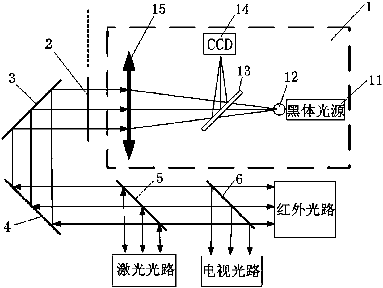
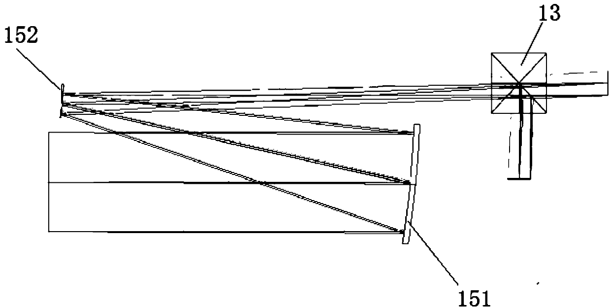
[0040] Such as figure 1 As shown, the airborne three optical axis consistency test system 1 of the present invention includes an airborne three optical axis consistency test assembly and a peripheral optical path, wherein the airborne three optical axis consistency test assembly includes a collimator 15, a beam splitter 13, Star point plate, CCD detector 14 and blackbody light source 11; one end of collimator 15 is the entrance of converging light, and the other end is the entrance of parallel light; beam splitter 13, target plate 12, CCD detector 14 and blackbody light source 11 are located The collimator 15 converges one end of the light entrance and exit; the target target plate 12 is located on the focal plane of the collimator 15; the black body light source 11 is used to illuminate the target target plate 12; the outgoing light of the target ta...


PUM


Abstract

The invention relates to an onboard three-optical-axis consistency test component, system and method. The test component comprises a collimator, a beam splitter, a target plate, a CCD detector and a blackbody light source; the beam splitter, the target plate, the CCD detector and the blackbody light source are positioned at one end of the converging light entrance of the collimator; the target plate is positioned on the focal plane of the collimator; the blackbody light source is used for illuminating the target plate; the emergent light of the target plate reaches the converging light entrance of the collimator via the beam splitter; and the emergent light of the converging light entrance of the collimator reaches the CCD detector via the beam splitter. The test method comprises the stepsof 1, transferring a datum; 2, testing the drift angle of the optical axis of the laser light path via the CCD detector; and 3, testing the respective drift angles of the television light path optical axis and the infrared light path optical axis via the blackbody light source. According to the component, system and method provided by the invention, the problems that the existing test system andmethod are limited in accuracy, large in optical adjustment difficulty and not applicable to being onboard are solved.

Description

technical field [0001] The invention belongs to the field of optical measuring instruments, and in particular relates to an airborne three-axis consistency test component, system and test method Background technique [0002] With the continuous application in the field of security reconnaissance and the increasingly complex application environment, in order to quickly and timely find the target in an all-weather environment and realize real-time tracking and accurate measurement of the target, the airborne optical sight has changed from the traditional single optical axis system Transformed into today's multiple small sub-optical systems. The consistency of the three optical axes of the optical sight, that is, the parallelism between the optical axes of the laser optical path, the optical axis of the TV optical path and the optical axis of the infrared optical path, has an important impact on the performance of the entire system. How to perform high-precision real-time dete...

Claims


Application Information

Patent Timeline
Patent Type & Authority Applications(China)
IPC IPC(8): G01M11/02
CPCG01M11/0221
Inventor 张玺斌高立民赵建科徐亮刘峰李朝辉李晓辉午建军
Owner XI'AN INST OF OPTICS & FINE MECHANICS - CHINESE ACAD OF SCI
Learn More