
Method for improving accuracy of signal recognition of unmanned aerial vehicle

A technology of signal recognition and UAV, applied in transmitter/receiver shaping network, baseband system, digital transmission system, etc., can solve problems such as difficult, inconspicuous infrared reflection characteristics, and large low-altitude blind area, etc., to achieve The effect of improving accuracy, improving system response sensitivity, and reducing calculation amount

Active Publication Date: 2019-04-05
北航(四川)西部国际创新港科技有限公司
View PDF4 Cites 5 Cited by
  • Summary
  • Abstract
  • Description
  • Claims
  • Application Information

AI Technical Summary

Problems solved by technology

These methods have their own characteristics: the disadvantage of radar detection is that the drone’s scattering area is small, which greatly reduces the distance and probability of being detected by radar, and the low-altitude blind area is large, making it very difficult for ground radar to detect drones; For photoelectric detection, under conditions such as thick clouds or backlighting, the difficulty of identification and tracking increases due to the lack of obvious infrared reflection characteristics of the target; for acoustic detection, the environmental background noise will affect the detection sensitivity and make it difficult to identify the target in places such as busy cities or airports. ;Due to the inevitability of communication between UAVs and operators, the radio signal spectrum detection technology that analyzes this signal interception is a UAV detection technology worthy of attention and in-depth research

Method used


Image

  • Method for improving accuracy of signal recognition of unmanned aerial vehicle
  • Method for improving accuracy of signal recognition of unmanned aerial vehicle
  • Method for improving accuracy of signal recognition of unmanned aerial vehicle

Examples


Embodiment Construction

[0029] In order to make the object, technical solution and advantages of the present invention clearer, the present invention will be further described in detail below in conjunction with the accompanying drawings and examples.

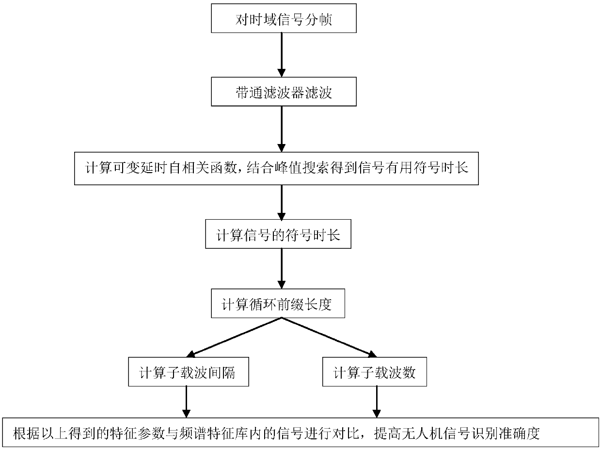
[0030] Such as figure 1 As shown, a method for improving the accuracy of UAV signal recognition includes the following steps:

[0031] Step 1: Initialize the signal processing environment and frame the time domain signal.

[0032] After initializing the software environment for back-end signal processing, the continuous sampled time-domain signal is processed in frames, and each frame signal is used as a unit for subsequent feature parameter extraction. In the signal frame processing, the sliding average window processing is mainly used to capture the rising and falling edges of the signal according to the set threshold.

[0033] Step 2: Pass the framed signal unit through a band-pass filter.

[0034] According to the time-domain frame processing i...


PUM


Abstract

The invention discloses a method for improving the accuracy of signal recognition of an unmanned aerial vehicle. The method comprises the following steps of: initializing a signal processing environment and framing a time domain signal; and passing the framed signal unit through a band pass filter; calculating variable delay autocorrelation function of a signal unit to combine the peak search to obtain the useful symbol duration of the signal; calculating the fixed delay cyclic spectrum function of the signal unit to combine the peak search to obtain the symbol duration of the signal; calculating the cyclic prefix length; calculating the subcarrier spacing of the signal; and calculating the number of subcarriers of the signal. The characteristic parameters calculated according to the abovesteps are compared with the signals in the spectrum feature library to achieve the classification and recognition of the signals transmitted by the unmanned aerial vehicle; the accuracy of the calculation of the characteristic parameters is effectively improved; the useful symbol duration is calculated at a faster speed; the amount of calculation is greatly reduced, and the system response sensitivity is improved; and a powerful support is provided for the subsequent demodulation and decoding of signals.

Description

technical field [0001] The invention relates to the technical field of electronic reconnaissance, in particular to a method for improving the accuracy of UAV signal recognition based on cyclostationarity detection. Background technique [0002] UAV (Unmanned Aerial Vehicles, UAV) originated in the military field. In the late 1990s, due to breakthroughs in the miniaturization and low-altitude technology of UAVs, the UAV market grew rapidly and was widely used in Agriculture, photography and other fields. As the global anti-terrorism situation becomes more and more serious, the number of illegally possessed drones has soared, which has brought a huge security threat to key targets, key areas and key activities. Once terrorists use drones to conduct The consequences of a terrorist attack would be disastrous. Due to its slow flying speed, low flying altitude, and small radar scattering area, some UAVs even use stealth coatings, which make it difficult to be detected by radar, ...

Claims


Application Information

Patent Timeline
IPC IPC(8): H04L25/03H04L27/26
CPCH04L25/03012H04L27/2602
Inventor 白琳张学军肖越
Owner 北航(四川)西部国际创新港科技有限公司
Learn More