Surface wiping structure for computer display screen

A display screen and computer technology, applied in the direction of pollution prevention methods, cleaning methods using tools, cleaning methods and appliances, etc. Dust effect and other issues, to achieve good use prospects, good practicability, and good adaptability

Active Publication Date: 2019-04-09
合肥金新允电子技术有限公司
9 Cites 2 Cited by

AI-Extracted Technical Summary

Problems solved by technology

[0002] A display is usually also called a monitor. A display is an I/O device belonging to a computer, that is, an input and output device. It is a display tool that displays certain electronic files on the screen through a specific transmission device and then reflects them to the human eye. According to different manufacturing materials, it can be divided into: cathode ray tube display, plasma display PDP, liquid crystal display LCD, etc., and the wiping structure is an...

Method used

It should be noted that the present invention is a surface wiping structure of a computer display screen. When in use, threaded column 5 runs through the inside of No. 2 splint 6 and No. 1 splint 3 simultaneously, and No. 2 splint 6 passes through threaded column 5 and the No. 1 splint 3 are fixedly installed, which can easily change the installation position of the No. 2 splint 6 on the threaded column 5 to change the distance between the No. 1 splint 3 and the No. 2 splint 6, so that the wiping structure can utilize the No. 2 splint 6, The No. 1 splint 3 can be clamped on display screen frames of different thicknesses, and the adaptability is better. The No. 1 rubber pad 4 on the No. 1 splint 3 and the No. 2 rubber pad 7 on the No. 2 splint 6 can be clamped. To ease the effect and avoid the wear and tear on the frame of the display screen, there are pen holders 2 distributed on the storage box 1, and the longitudinal diamet...

Abstract

The invention discloses a surface wiping structure for a computer display screen. The surface wiping structure for the computer display screen comprises a holding box and a support rod, wherein a pencontainer is arranged on the outer wall of the holding box; a No.1 clamping plate is adhered to the outer surface of one side of the holding box; a No.1 rubber pad is adhered to the outer surface of one side of the No.1 clamping plate; a threaded column is rotatably arranged on the inner surface of the No.1 clamping plate; a No.2 clamping plate is arranged on the outer surface of the threaded column; a No.2 rubber pad is adhered to the outer surface of one side of the No.2 clamping plate; a dustproof box is arranged on the outer surface of the upper end of a support rod; a magnet is arranged on the outer surface of the lower end of the dustproof box; a holding hole is formed in the outer wall of the dustproof box; cleaning sponge is placed in the holding hole; a pull ring is arranged on the outer surface of the upper end of the cleaning sponge; and a retaining ring is sleeved in the cleaning sponge. The surface wiping structure for the computer display screen provided by the inventionhas good portability and adaptability, can be taken on demand, is convenient to adapt, has a dustproof effect, and brings a better use prospect.

Application Domain

Fouling preventionCleaning using tools

Technology Topic

Surface bondingRetaining ring +2

Image

  • Surface wiping structure for computer display screen
  • Surface wiping structure for computer display screen
  • Surface wiping structure for computer display screen

Examples

  • Experimental program(1)

Example Embodiment

[0018] In order to make the technical means, creative features, goals and effects achieved by the present invention easy to understand, the present invention will be further described below in conjunction with specific embodiments.
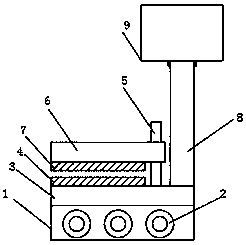
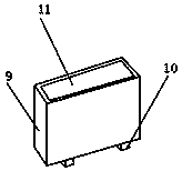
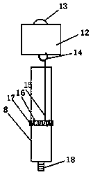
[0019] like Figure 1-3 As shown, a surface wiping structure of a computer display screen includes a housing box 1 and a support rod 8, a pen holder 2 is opened on the outer wall of the housing box 1, and a No. 1 splint 3 is bonded to the outer surface of one side of the housing box 1, One side outer surface of the No. 1 splint 3 is bonded with a No. 1 rubber pad 4, and the inner surface of the No. 1 splint 3 is rotatably installed with a threaded post 5, and the outer surface of the threaded post 5 is equipped with a No. 2 splint 6, and the No. 2 splint The outer surface of one side of 6 is bonded with No. 2 rubber pad 7, the outer surface of the upper end of the support rod 8 is provided with a dustproof box 9, and the outer surface of the lower end of the dustproof box 9 is provided with a magnet 10, and the outer wall of the dustproof box 9 There is a holding hole 11 on the top, and a cleaning sponge 12 is placed in the holding hole 11. A pull ring 13 is provided on the outer surface of the upper end of the cleaning sponge 12, and a buckle 14 is set inside the cleaning sponge 12, and the outer surface of the buckle 14 is bolted. A traction rope 15 is installed, and the traction rope 15 is wound with a winding rod 16, the outer surface of the winding rod 16 is provided with a torsion spring 17, and the outer surface of the lower end of the support rod 8 is provided with a threaded bolt 18, and the torsion spring 17 is sleeved on the support the interior of rod 8;
[0020] The longitudinal diameter specifications of the pen holder 2 are from large to small, and the quantity of the pen holder 2 is three groups, and the pen holders 2 are respectively placed in parallel; there are installation holes on the outer wall of the storage box 1, and the storage box 1 passes through the installation hole and the screw thread of the support rod 8 The bolt 18 is rotated and installed; the threaded column 5 runs through the inside of the No. 2 splint 6 and the No. 1 splint 3 at the same time, and the No. 2 splint 6 is fixedly installed with the No. 1 splint 3 through the threaded column 5; the cleaning sponge 12 is a square structure. Parts, and the size of the cleaning sponge 12 is slightly smaller than the size of the housing hole 11; the No. 1 rubber pad 4 is constructed of a rubber material, and the outer surface of the No. 1 rubber pad 4 is coated with a hydrophobic and oleophobic layer; the support rod 8 is A cylindrical hollow structure, and the support rod 8 is made of steel.
[0021] It should be noted that the present invention is a surface wiping structure of a computer display screen. When in use, the threaded column 5 penetrates the inside of the No. 2 splint 6 and the No. 1 splint 3 at the same time, and the No. The No. 3 splint 3 is fixedly installed, which can easily change the installation position of the No. 2 splint 6 on the threaded column 5 to change the distance between the No. 1 splint 3 and the No. 2 splint 6, so that the wiping structure can use the No. 2 splint 6 and the No. 1 splint. 3. It can be clamped on display screen frames of different thicknesses, and has better adaptability. The No. 1 rubber pad 4 on the No. 1 splint 3 and the No. 2 rubber pad 7 on the No. 2 splint 6 can play a role of relaxation when clamping. function, to avoid wear and tear on the frame of the display screen, there are pen holders 2 distributed on the storage box 1, and the longitudinal diameters of the pen holders 2 are from large to small, which can facilitate the placement of pens of different sizes. The traction rope 15 is wound on the winding rod 16, and the winding rod 16 is connected with the support rod 8 through the torsion spring 17, and the cleaning sponge 12 is pulled out through the pull ring 13 on the cleaning sponge 12, and the traction rope 15 is wiped according to the actual wiping range of the user. Rotate the winding rod 16 to extend a longer traction rope 15. When the user puts the cleaning sponge 12 back into the dustproof box 9, the torsion spring 17 will drive the winding rod 16 to rotate to extend the stretched rope after losing tension. Traction rope 15 is retracted, and dust-proof box 9 can play the effect of dust-proof and ash-proof, avoids the long-term idle cleaning sponge 12 from becoming dirty, and is comparatively practical.
[0022] The basic principles and main features of the present invention and the advantages of the present invention have been shown and described above. Those skilled in the industry should understand that the present invention is not limited by the above-mentioned embodiments. What are described in the above-mentioned embodiments and the description only illustrate the principle of the present invention. Without departing from the spirit and scope of the present invention, the present invention will also have Variations and improvements are possible, which fall within the scope of the claimed invention. The protection scope of the present invention is defined by the appended claims and their equivalents.

PUM

no PUM

Description & Claims & Application Information

We can also present the details of the Description, Claims and Application information to help users get a comprehensive understanding of the technical details of the patent, such as background art, summary of invention, brief description of drawings, description of embodiments, and other original content. On the other hand, users can also determine the specific scope of protection of the technology through the list of claims; as well as understand the changes in the life cycle of the technology with the presentation of the patent timeline. Login to view more.

Similar technology patents

Three-waveband target surface temperature inversion method

PendingCN111721423AImprove inversion accuracyGood adaptability
Owner:中国人民解放军63660部队

Machine bottom surface spraying equipment

Owner:西安通用开关电气有限公司

Oil filling nozzle

InactiveCN102943952AGood adaptabilityEasy to fill oil
Owner:SUZHOU BLUE KING MACHINE TOOL TECH CO LTD

Classification and recommendation of technical efficacy words

  • avoid getting dirty
  • Good adaptability

pencil sharpener with clip

InactiveCN102275435Aavoid getting dirty
Owner:龚晓涛
Why Eureka
Try Eureka