Eureka AIR delivers breakthrough ideas for toughest innovation challenges, trusted by R&D personnel around the world.

Grid tray part machining method

A processing method and grid plate technology are applied in the processing field of grid plate parts, which can solve the problems of high machining accuracy and surface roughness requirements of parts.

Active Publication Date: 2019-04-09
CHINA NUCLEAR BAOTOU GUANGHUA CHEM IND
View PDF12 Cites 0 Cited by
  • Summary
  • Abstract
  • Description
  • Claims
  • Application Information

AI Technical Summary

Problems solved by technology

This component is produced for the first time in China, and requires high processing precision and surface roughness. It is also a nuclear fuel component, and there are no reports in related fields.

Method used


Image

  • Grid tray part machining method
  • Grid tray part machining method
  • Grid tray part machining method

Examples


Embodiment Construction

[0015] The present invention will be described in detail below in conjunction with the accompanying drawings and specific embodiments.

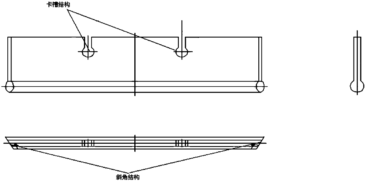
[0016] Such as figure 1 Shown is the part diagram of the grid plate, according to the requirements of the shape and size accuracy of the grid plate, and the surface roughness requirements, the present invention adopts the wire cutting method to complete the processing. Grid plate processing is divided into shape cutting, slot cutting and bevel cutting. The shape processing adopts wire cutting processing to complete the processing of the elongated thin plate with a match head shape.

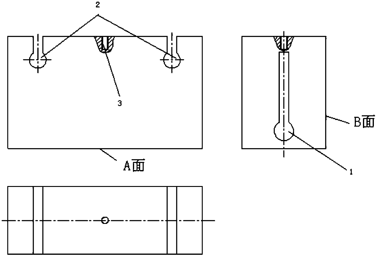
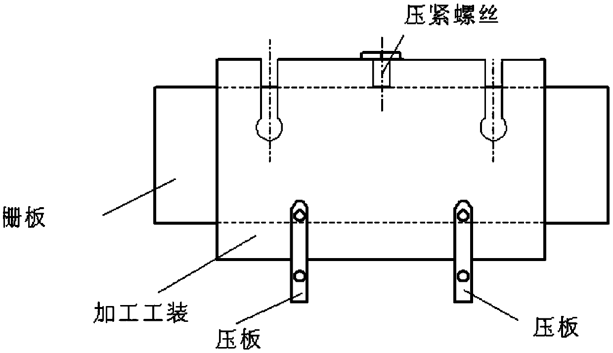
[0017] Card slot and bevel processing tooling design: stainless steel material, design and processing as follows figure 2 tooling to realize wire cutting processing of slots and bevels. The overall shape of the tooling is a cuboid, with a matchhead-shaped through groove running through the front and back, that is, groove B2, and a matchhead-shaped groove A1 r...


PUM


Abstract

The invention belongs to the technical field of nuclear fuel element machining, and particularly relates to a grid tray part machining method. The outline of a whole clamping groove and bevel angle machining tool is cuboid, the front surface and the rear surface of the machining tool are provided with match-head-shaped through grooves B in a penetrating mode, the left surface and the right surfaceare provided with match-head-shaped grooves A in a penetrating mode, and a threaded hole is vertically machined in the upper surface so that a pressing screw can be tightened; after grid tray outlinemachining and match-head outline cross-section sheet machining are completed, match-head outline cross-section sheets are inserted in the grooves A, through tool aligning, it is ensured that a grid tray coincides with the center of the tool and is pressed through the pressing screw, the tool makes contact with the table top of wire-electrode cutting equipment and is horizontally placed and pressed by a pressing plate, grid tray clamping groove structures are machined at the grooves B, and clamping groove machining is completed; and after clamping groove machining is completed, the tool is turned over by 90 degrees, the tool makes contact with the table top of wire-electrode cutting equipment and is horizontally placed and pressed by the pressing plate, and bevel angle machining is completed. The grid tray part machining method can meet the machining requirements for grid tray parts.

Description

technical field [0001] The invention belongs to the technical field of nuclear fuel element processing, and in particular relates to a processing method of grid plate parts. Background technique [0002] The grid plate mainly realizes the connection between the end plug and the grid plate frame, and the connection between the lower transition joint and the pins. Through its special shape, high precision processing, and high surface quality, the accuracy and quality of component assembly and welding are guaranteed. The grid plate is a key part of the fast reactor assembly. Its structure is a slender thin plate with a special-shaped cross-section in the shape of a matchhead. This component is produced for the first time in China, and requires high processing precision and surface roughness. It is also a nuclear fuel component, and there are no reports in related fields. Contents of the invention [0003] The purpose of the present invention is to provide a processing method...

Claims


Application Information

Patent Timeline
Patent Type & Authority Applications(China)
IPC IPC(8): B23H7/02
CPCB23H7/02
Inventor 郭燕芳张力韩志华马建
Owner CHINA NUCLEAR BAOTOU GUANGHUA CHEM IND
Why Eureka
Eureka Blog
Learn More