Manufacturing method of integral bent lap joint type frame

A manufacturing method and overall technology, applied in the direction of electrical components, circuits, battery pack parts, etc., can solve the problems of high processing cost, increased processing cost, large number of tooling fixtures, etc., and achieve less man-hours, easy processing, and low cost. Effect

Active Publication Date: 2019-04-09
东风时代(武汉)电池系统有限公司
View PDF11 Cites 2 Cited by
  • Summary
  • Abstract
  • Description
  • Claims
  • Application Information

AI Technical Summary

Problems solved by technology

[0006] 1. With multiple welding parts, the overall structural strength cannot be guaranteed, which will inevitably lead to different connection strengths of the four welding points;
[0007] 2. The quadrilateral obtained by welding cannot be guaranteed to be completely on the same plane, causing subsequent warping, which req

Method used


Image

  • Manufacturing method of integral bent lap joint type frame
  • Manufacturing method of integral bent lap joint type frame
  • Manufacturing method of integral bent lap joint type frame

Examples


Embodiment 1

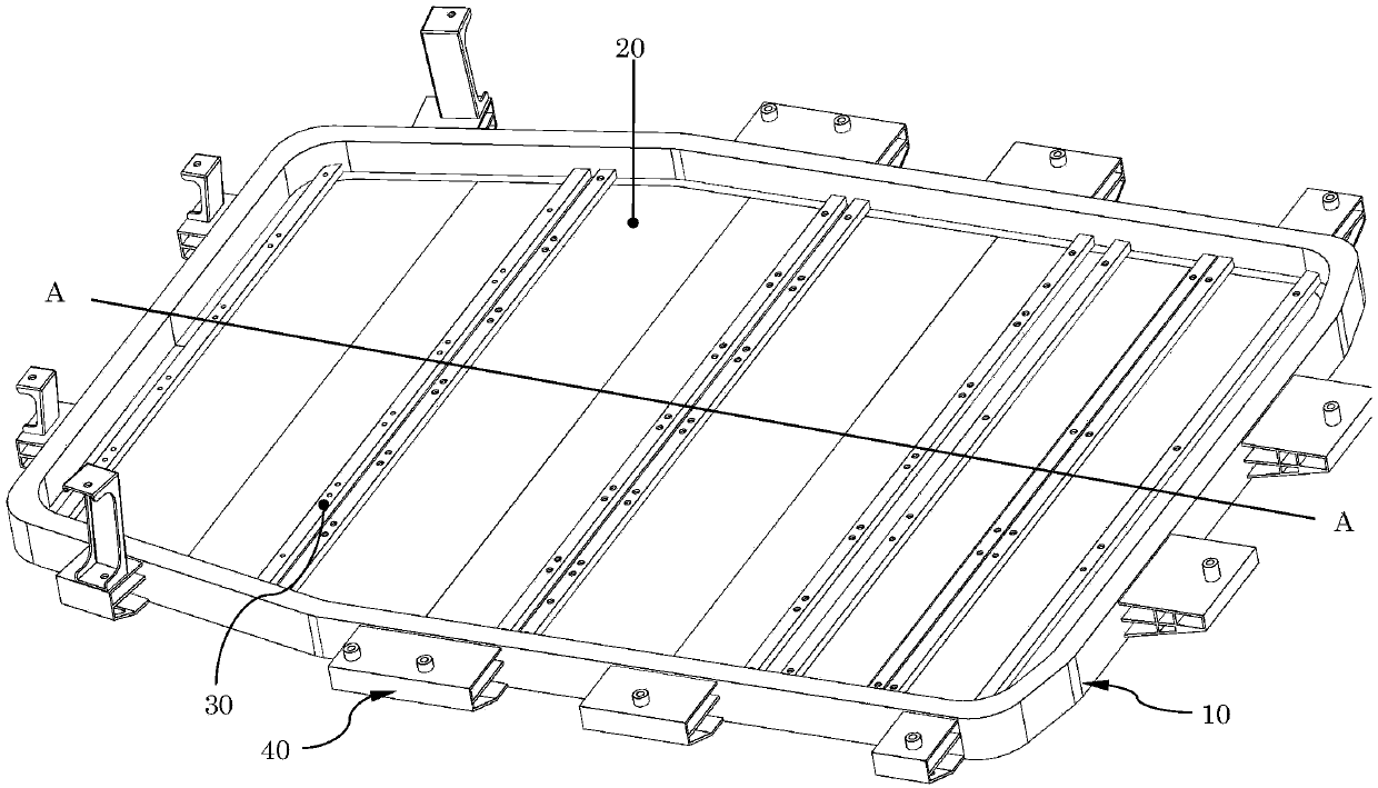
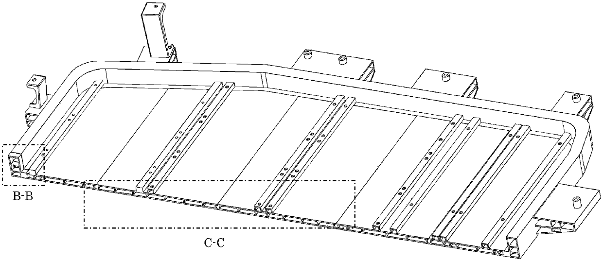
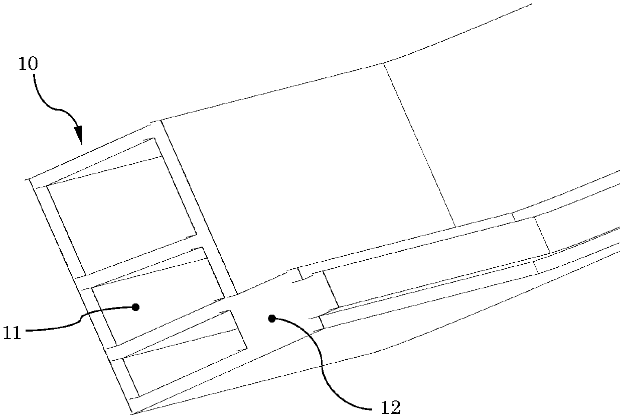
[0058] Such as figure 1 , 2 As shown in , 3, the overall bending and overlapping frame includes:

[0059] The ring beam assembly 10 is a closed ring formed by bending and connecting ring beam profiles.

[0060] The bottom plate 20 is snapped into the ring beam assembly.

[0061] The support rod 30 is used to connect and fix the bottom plate on the ring beam assembly.

[0062] The method for making the above frame includes the following steps:

[0063] Step 1, processing the predetermined length of the ring beam profile into an unconnected closed ring;

[0064] Step 2. Stretch the unconnected and closed circle, and insert the bottom plate;

[0065] Step 3: Connect and fix the parts near both ends of the support rod with the ring beam profile, and connect the middle part of the two ends with the bottom plate, so that the bottom plate is connected and fixed by the support rod in the above-mentioned unconnected closed circle;

[0066] Step 4. Close the unconnected closed cir...

Embodiment 2

[0068] As an optimized operation, the fourth step of closing the unconnected closed circle and connecting includes the following operations:

[0069] Fix the ends of the unconnected loops on the two welding heads of the resistance welding machine, and apply pressure to close the welded connection.

[0070]In this embodiment, a resistance welding machine is used, preferably a spot welding machine. Fix the two spot welding arms of the spot welding machine to the two ends of the unconnected ring, and then pressurize and energize to complete the welding.

Embodiment 3

[0072] Further, in order to better ensure that the butt joint is accurate during welding and no deflection occurs, on the basis of Example 2, the two ends of the unconnected rings are inserted into the positioning sleeve during operation, and the two unconnected rings are pressurized so that the two unconnected The ends are aligned exactly. The positioning sleeve is in the shape of a tube, which just fits the ring beam profile, so under the constraint of the ring beam profile positioning sleeve, warping caused by thermal deformation is not easy to occur during welding.


PUM


Abstract

The invention provides a manufacturing method of an integral bent lap joint type frame. The integral bent lap joint type frame comprises a ring beam assembly, a bottom plate and supporting rods, wherein the ring beam assembly is a closed ring which is formed by connecting a ring beam profile in a bent mode; the bottom plate is clamped in the ring beam assembly; and the supporting rods are used forconnecting and fixing the bottom plate to the ring beam assembly. The manufacturing method comprises the following steps that the ring beam profile with the preset length is machined into the non-connected and closed ring; the bottom plate is sleeved with the non-connected and closed ring; and the parts, close to the two ends, of the supporting rods are fixedly connected with the ring beam sectional material, and the middle parts at the two ends are connected with the bottom plate, so that the bottom plate is connected and fixed in the non-connected and closed ring by the supporting rods; andthe non-connected closed ring is closed and connected. According to the method, the processing is easy, the working hours are few, and the cost is low; and meanwhile, the ring beam assembly is obtained by bending the sectional material and then connecting and fixing the section at a time, the flatness is high, a machining tool is simple, and a plurality of complex tool clamps are not needed.

Description

technical field [0001] The invention relates to a shell of a battery pack of an electric vehicle, in particular to a method for manufacturing an integrally bent and lapped frame, and belongs to the field of mechanical structures. Background technique [0002] The casing of the existing electric vehicle battery pack usually includes an upper casing and a lower casing. The usual lower casing is required to have a Certain mechanical strength. [0003] The existing lower casing includes a frame beam and a bottom arranged in the frame beam, wherein the frame is used as the skeleton of the lower casing, and the bottom plate is used as a support to fill the whole frame and seal the bottom of the battery pack. [0004] Now a commonly used design is to use four sections of rods to weld and splice at the end to obtain a quadrilateral frame, and then fix the whole or multiple sheets to the frame. [0005] However, the above structure finds the following deficiencies in actual use: ...

Claims


Application Information

Patent Timeline
IPC IPC(8): B23P15/00H01M2/10H01M50/20
CPCB23P15/00H01M50/20Y02E60/10
Inventor 黄希光
Owner 东风时代(武汉)电池系统有限公司
Why Eureka
Try Eureka