
Automobile brake caliper body

A technology of brake calipers and automobiles, which is applied in the direction of vehicle components, cooling brakes, brakes, etc., can solve the problems of slow response speed and single form, and achieve the effects of strong braking, improved safety, and accelerated braking action

Pending Publication Date: 2019-04-09
CHANGZHOU VOCATIONAL INST OF ENG
View PDF0 Cites 0 Cited by
  • Summary
  • Abstract
  • Description
  • Claims
  • Application Information

AI Technical Summary

Problems solved by technology

[0005] The purpose of the present invention is to overcome the shortcomings of the existing automobile brake caliper body such as single form and slow response speed, and provide an automobile brake caliper body. By adopting the technical solution of the present invention, main brake mechanisms are arranged on both sides of the brake disc. After stepping on the brake pedal, the electromagnetic brake system in the main brake mechanism responds quickly and uses the brake pads to brake the brake disc, and the hydraulic brake system further increases the braking force of the brake pads, which not only speeds up the response speed, but also prevents Problems such as inability to turn caused by excessive locking force on the wheel at one time greatly improve the safety of use and prolong the service life of the brake; at the same time, the pulse auxiliary braking system and the metal expansion auxiliary braking system are used for further auxiliary braking. , making the braking performance of the automobile brake caliper more reliable and stable

Method used


Image

  • Automobile brake caliper body
  • Automobile brake caliper body
  • Automobile brake caliper body

Examples


Embodiment

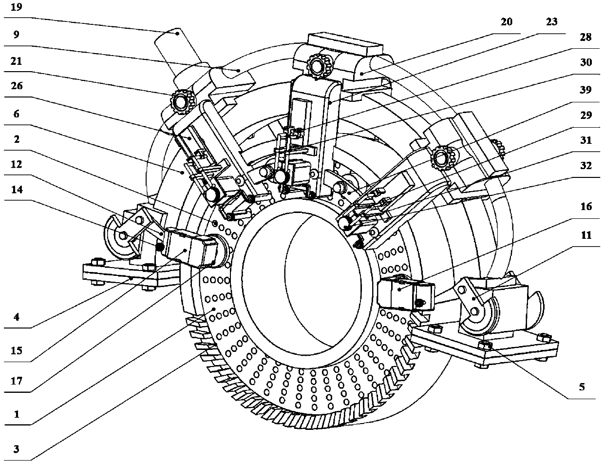
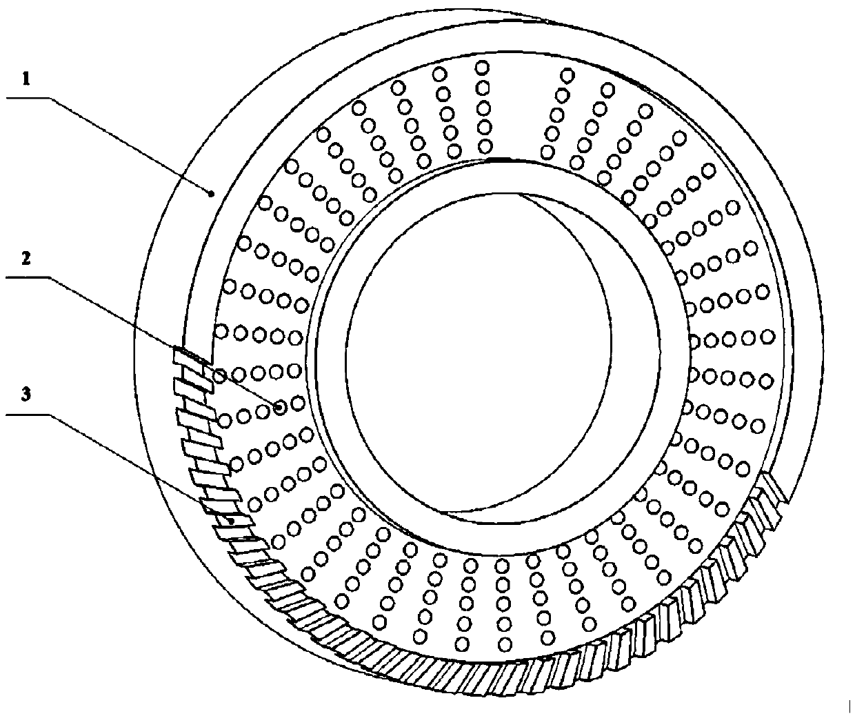
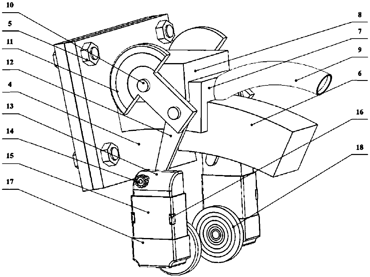
[0043] combine figure 1 , figure 2 , Figure 5 and Figure 13 As shown, a kind of automobile brake caliper body of the present embodiment includes a brake disc 1 connected to the axle of the automobile, a main brake system matched with the brake disc 1 and a base frame system for installing the main brake system, and the brake disc 1 is provided with There are several heat dissipation holes 2, and the bottom of the brake disc 1 is provided with a heat conduction groove 3, which enhances the heat conduction efficiency of air cooling and oil cooling. The base frame system includes a supporting beam 6 and connecting plates 4 arranged at both ends of the supporting beam 6 for connecting with the vehicle body. The connecting plate 4 is fixedly connected to the vehicle body through fastening screws 5 . The main brake mechanism is installed in the middle of the support beam 6, and the main brake system has two sets of opposite main brake mechanisms located on both sides of the br...


PUM


Abstract

The invention discloses an automobile brake caliper body and belongs to the technical field of automobile brake equipment. The automobile brake caliper body comprises a brake disc, a main brake systemand a base frame system. The main brake system is provided with main brake mechanisms. Each main brake mechanism comprises an electromagnetic brake system and an oil pressure brake system. Each oil pressure brake system comprises a pressurizing mechanism, an oil pressure tank and a brake pad. Each brake pad is connected with the front end of a push plate arranged in the corresponding oil pressuretank. The rear end of each push plate is connected with the rear part of a shell through a spring. Each pressurizing mechanism is connected with the rear part of the corresponding oil pressure tank through a pipeline. According to the automobile brake caliper body, the main brake mechanisms are arranged on both sides of the brake disc, the electromagnetic brake systems in the main brake mechanisms make a rapid respond and brake the brake disc, and the braking force of the brake pads is further increased by the oil pressure brake systems, so that the response speed is increased, the problems of steering failure and the like caused by too large one-time locking force on wheels can be prevented as well, the use safety is greatly improved, and the service life of the brake is prolonged.

Description

technical field [0001] The invention relates to the technical field of automobile braking equipment, and more specifically relates to an automobile brake caliper body. Background technique [0002] The automobile industry is one of the largest and most important industries in the world. In a sense, the development level and strength of the automobile industry reflect the comprehensive national strength and competitiveness of a country. As an extremely important part of automobiles, automobile brakes are People should pay enough attention to it, but the current automobile brake device is mainly a simple butterfly brake device, which has problems such as easy skidding of the brake and lack of brake control functions. [0003] In order to solve the above problems, relevant technical personnel have made some improvements, such as Chinese patent number ZL201410416600.6, the date of authorization announcement is August 17, 2016, and the name of the invention is: a brake clutch dev...

Claims


Application Information

Patent Timeline
Patent Type & Authority Applications(China)
IPC IPC(8): B60T13/74B60T13/14B60T13/58B60T5/00
CPCB60T13/14B60T13/58B60T13/741B60T5/00
Inventor 于瑞姜程杨刘永发
Owner CHANGZHOU VOCATIONAL INST OF ENG
Learn More