High-speed hot cutter slitting device and control method thereof

A high-speed, hot-knife technology, applied in the control field of high-speed hot-knife slitting device and high-speed hot-knife slitting device, can solve the problems of long adjustment time, low efficiency, low precision, etc., achieve good dynamic balance effect and shorten movement distance, effects that improve accuracy

Inactive Publication Date: 2019-04-09
XIAN UNIV OF TECH
View PDF7 Cites 0 Cited by
  • Summary
  • Abstract
  • Description
  • Claims
  • Application Information

AI Technical Summary

Problems solved by technology

[0002] After the laminating machine completes the laminating work, the printed products one by one are continuously placed on the conveyor belt, and the printed products are sent to the hot knife slitting unit by the conveyor belt. Since the hot knife slitting unit has no front gauge mechanism, the printed product The front edge cannot be accurately positioned, so the hot knife slitting unit needs to be equipped with a detection device. Most of the hot knife slitting units use photoelectric detection mechanisms or laser sensors for detection; secondly, the hot knife slitting unit on the laminating machine, Most of the tool holder structures used are hexahedral tool holders or inverted H-shaped tool holders, which can only complete two cuts in one rotation, which is inefficient and a serious waste of resources.
The adjustment mechanism of the hot knife cutting unit on the existing laminating machine only adjusts one side, and the other side is only fixed by a hinge or bearing mechanism, and one side is adjusted. The adjustment time is long, and the angle of rotation of the hot knife shaft is large. , low precision, scratches, burrs and other defects on the printed product after cutting, resulting in a serious waste of resources, so the detection, control and adjustment of the hot knife slitting unit are very important

Method used


Image

  • High-speed hot cutter slitting device and control method thereof
  • High-speed hot cutter slitting device and control method thereof
  • High-speed hot cutter slitting device and control method thereof

Examples


Embodiment Construction

[0023] The present invention will be described in detail below in conjunction with the accompanying drawings and specific embodiments.

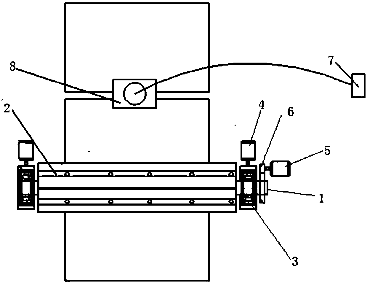
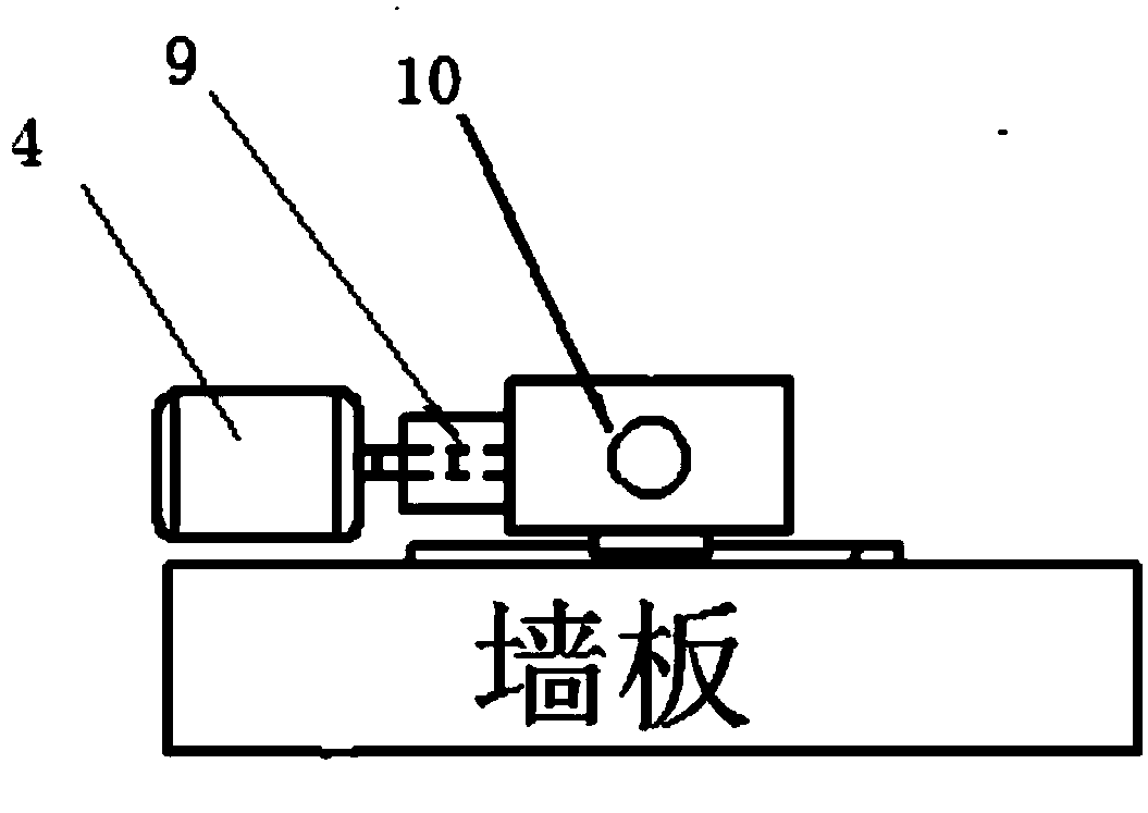
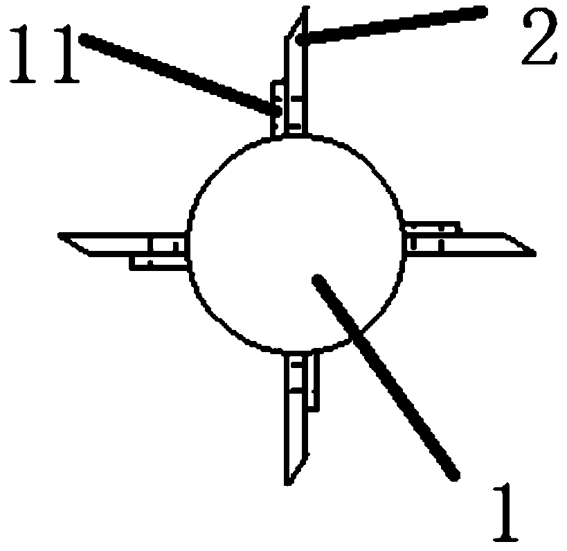
[0024] The invention provides a high-speed hot knife cutting device, such as figure 1 As shown, including the main shaft 1, a thermal blade 2 is arranged along the axis of the main shaft 1, and the thermal blade 2 is four blades perpendicular to each other, as image 3 Heating wires 11 are respectively arranged in the shown hot blade 2, self-aligning bearings 3 matched with the main shaft 1 are respectively arranged at both ends of the main shaft 1, and the surface of the self-aligning bearing 3 is also provided with a servo drive perpendicular to the outer surface of the main shaft 1. The motor 4 and the servo motor 4 are connected to the self-aligning bearing 3 through a ball screw 9, and one end of the main shaft 1 is also provided with a driving motor 5, and the main shaft of the driving motor 5 is connected to the main shaft 1 through a ...


PUM


Abstract

The invention discloses a high-speed hot cutter slitting device. The high-speed hot cutter slitting device comprises a main shaft, and a hot blade is arranged along the axis of the main shaft, the twoends of the main shaft are provided with a self-aligning bearing matched with the main shaft correspondingly, and a servo motor perpendicular to the main shaft is further arranged on the surface of the self-aligning bearing; a driving motor is further arranged at one end of the main shaft, and the driving motor is connected with the main shaft through a synchronous belt; and the high-speed hot cutter slitting device further comprises a control system, the control system is connected with a CCD image sensor, the servo motor and the driving motor. According to the device, dynamic balance performance is good, the adjusting precision is high, the left end and the right end can be adjusted at the same time, and the adjusting speed is high.

Description

technical field [0001] The invention belongs to the field of post-press equipment, and relates to a high-speed hot knife slitting device, and also relates to a control method of the above-mentioned high-speed hot knife slitting device. Background technique [0002] After the laminating machine completes the laminating work, the printed products one by one are continuously placed on the conveyor belt, and the printed products are sent to the hot knife slitting unit by the conveyor belt. Since the hot knife slitting unit has no front gauge mechanism, the printed product The front edge cannot be accurately positioned, so the hot knife slitting unit needs to be equipped with a detection device. Most of the hot knife slitting units use photoelectric detection mechanisms or laser sensors for detection; secondly, the hot knife slitting unit on the laminating machine, Most of the tool holders used are hexahedral tool holders or inverted H-shaped tool holders, which can only complete...

Claims


Application Information

Patent Timeline
Patent Type & Authority Applications(China)
IPC IPC(8): B65H35/06
CPCB65H35/06
Inventor 赵庆海石玉霞徐卓飞闫鹏鑫刘东
Owner XIAN UNIV OF TECH
Why Eureka
Try Eureka